Build package
Build AR4
Annin Robotics · Arm · active
Open-plan, low-cost 6-DOF desktop industrial-style robot arm by Chris Annin, programmable via its HMI, Python or ROS.
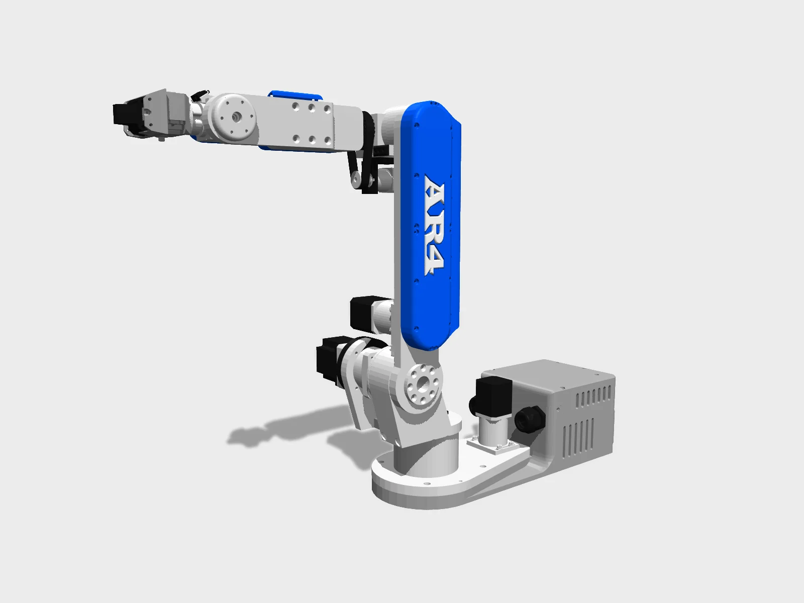
- Drawing
- /anninrobotics/ar4
- Maker
- Annin Robotics
- Country
- US
- Package rev
- v0.1.0
- Level
- L1 Compiled
- Availability
- Kit
- Openness
- 90/100
- HW licence
- Annin-Robotics-NC-1.1
- Last checked
- 2026-09-25
- DOF
- 6
Chris Annin declared the design complete with the final Mark 5 revision. ar4_ros_driver is MIT; ar4-hmi uses the Annin Robotics Open Source Non-Commercial License v1.1 (GitHub NOASSERTION), recorded as LicenseRef-Annin-Robotics-NC-1.1. The design files (STLs in ar4-hmi) fall under the same non-commercial license, so hw is LicenseRef-Annin-Robotics-NC-1.1: no commercial use, no rehosting. The current build is MK5 (AR4-MK5 build manual v1.1 on the downloads page). STL files are free; SolidWorks/STEP CAD for MK5 is sold separately ($99). sim=true refers to URDF in the ROS driver repo.
Configure
Saved in the URL. Share the link to share the build.Source
One cart across 2 vendors · prices in USD as listedAnnin Robotics sells a kit. Buying from the maker funds the people who opened the design. Lines they stock are listed first below.
64 lines · 127 parts · 2 without an offer in US · 10/64 lines sourced in 2+ regions (L3 gate)
| # | Part | Category | Qty | Unit | Line | Offer |
|---|---|---|---|---|---|---|
Annin RoboticsMaker52 lines · $699.00 + 51 unpriced | ||||||
| 1 | AR4 MK5 Aluminum Parts Kit (26 machined structural pieces) structure.mk5-aluminum-kit · 1 alt | structure | 1 | $699.00 | $699.00 | Annin Robotics |
| 2 | 32009 taper roller bearing 45x75x20 mm (J1) structure.bearing-32009 · MPN 32009 | structure | 2 | unpriced | — | Annin RoboticsPart of the AR4 MK5 Hardware Kit, $319 for the whole kit (also inside the $1,189 MK5 Combo Kit) |
| 3 | 30206 taper roller bearing 30x62x17.25 mm (J2) structure.bearing-30206 · MPN 30206 | structure | 2 | unpriced | — | Annin RoboticsPart of the AR4 MK5 Hardware Kit, $319 for the whole kit (also inside the $1,189 MK5 Combo Kit) |
| 4 | 30204 taper roller bearing 20x47x15.25 mm (J3) structure.bearing-30204 · MPN 30204 | structure | 1 | unpriced | — | Annin RoboticsPart of the AR4 MK5 Hardware Kit, $319 for the whole kit (also inside the $1,189 MK5 Combo Kit) |
| 5 | AXK3552 thrust needle bearing 35x52x4 mm with AS3552 washers (J3) structure.bearing-axk3552 · MPN AXK3552 | structure | 1 | unpriced | — | Annin RoboticsPart of the AR4 MK5 Hardware Kit, $319 for the whole kit (also inside the $1,189 MK5 Combo Kit) |
| 6 | NTA1625 thrust needle bearing, 1.00 x 1.5625 x 0.0781 in (J4, J5, J6) structure.bearing-nta1625 · MPN NTA1625 | structure | 3 | unpriced | — | Annin RoboticsPart of the AR4 MK5 Hardware Kit, $319 for the whole kit (also inside the $1,189 MK5 Combo Kit) |
| 7 | TRA1625 thrust washer, 1.000 x 1.5625 x 0.0312 in structure.washer-tra1625 · MPN TRA1625 | structure | 4 | unpriced | — | Annin RoboticsPart of the AR4 MK5 Hardware Kit, $319 for the whole kit (also inside the $1,189 MK5 Combo Kit) |
| 8 | TRD1625 thrust washer, 1.000 x 1.5625 x 0.125 in structure.washer-trd1625 · MPN TRD1625 | structure | 2 | unpriced | — | Annin RoboticsPart of the AR4 MK5 Hardware Kit, $319 for the whole kit (also inside the $1,189 MK5 Combo Kit) |
| 9 | B1616 needle roller bearing, 1 x 1-1/4 x 1 in (J4 turret) structure.bearing-b1616 · MPN B1616 | structure | 2 | unpriced | — | Annin RoboticsPart of the AR4 MK5 Hardware Kit, $319 for the whole kit (also inside the $1,189 MK5 Combo Kit) |
| 10 | HK1612 needle roller bearing 16x22x12 mm (J5 idler) structure.bearing-hk1612 · MPN HK1612 | structure | 1 | unpriced | — | Annin RoboticsPart of the AR4 MK5 Hardware Kit, $319 for the whole kit (also inside the $1,189 MK5 Combo Kit) |
| 11 | 688Z groove ball bearing 8x16x5 mm (J5 lead screw end) structure.bearing-688z · MPN 688Z | structure | 1 | unpriced | — | Annin RoboticsPart of the AR4 MK5 Hardware Kit, $319 for the whole kit (also inside the $1,189 MK5 Combo Kit) |
| 12 | 30203 taper roller bearing 17x40x13.25 mm (J6) structure.bearing-30203 · MPN 30203 | structure | 1 | unpriced | — | Annin RoboticsPart of the AR4 MK5 Hardware Kit, $319 for the whole kit (also inside the $1,189 MK5 Combo Kit) |
| 13 | 3 mm x 85 mm shaft (J5 carrier guide rods; usually sold as 100 mm, cut to 85 mm) structure.rod-3x85 | structure | 2 | unpriced | — | Annin RoboticsPart of the AR4 MK5 Hardware Kit, $319 for the whole kit (also inside the $1,189 MK5 Combo Kit) |
| 14 | Brass bushing 3 mm ID x 7 mm OD x 20 mm (J5 carrier) structure.bushing-3x7x20 | structure | 2 | unpriced | — | Annin RoboticsPart of the AR4 MK5 Hardware Kit, $319 for the whole kit (also inside the $1,189 MK5 Combo Kit) |
| 15 | 60T XL timing pulley (J1; black phenolic from Amazon/ServoCity works, a print file is also provided) structure.pulley-xl-60t | structure | 1 | unpriced | — | Annin RoboticsPart of the AR4 MK5 Hardware Kit, $319 for the whole kit (also inside the $1,189 MK5 Combo Kit) |
| 16 | HTD 550-5M belt (J3) structure.belt-htd-550-5m · MPN HTD 550-5M | structure | 1 | unpriced | — | Annin RoboticsPart of the AR4 MK5 Hardware Kit, $319 for the whole kit (also inside the $1,189 MK5 Combo Kit) |
| 17 | 180XL037 timing belt (J1) structure.belt-180xl037 · MPN 180XL037 | structure | 1 | unpriced | — | Annin RoboticsPart of the AR4 MK5 Hardware Kit, $319 for the whole kit (also inside the $1,189 MK5 Combo Kit) |
| 18 | 150XL037 timing belt (J5) structure.belt-150xl037 · MPN 150XL037 | structure | 1 | unpriced | — | Annin RoboticsPart of the AR4 MK5 Hardware Kit, $319 for the whole kit (also inside the $1,189 MK5 Combo Kit) |
| 19 | 84XL037 timing belt (J4) structure.belt-84xl037 · MPN 84XL037 | structure | 1 | unpriced | — | Annin RoboticsPart of the AR4 MK5 Hardware Kit, $319 for the whole kit (also inside the $1,189 MK5 Combo Kit) |
| 20 | HTD 20 tooth pulleys, one long and one short shoulder (J3) structure.pulley-htd-20 | structure | 2 | unpriced | — | Annin RoboticsPart of the AR4 MK5 Hardware Kit, $319 for the whole kit (also inside the $1,189 MK5 Combo Kit) |
| 21 | XL 15 tooth pulley, 8 mm bore (J1 motor and J6 housing post; the J1 one needs a 3 mm key broach) structure.pulley-xl-15t-8mm | structure | 2 | unpriced | — | Annin RoboticsPart of the AR4 MK5 Hardware Kit, $319 for the whole kit (also inside the $1,189 MK5 Combo Kit) |
| 22 | XL 10 tooth pulley, 6 mm bore (J4 motor) structure.pulley-xl-10t-6mm | structure | 1 | unpriced | — | Annin RoboticsPart of the AR4 MK5 Hardware Kit, $319 for the whole kit (also inside the $1,189 MK5 Combo Kit) |
| 23 | 8 mm keyed rotary shaft, 50 mm long (J3) structure.shaft-8mm-keyed | structure | 1 | unpriced | — | Annin RoboticsPart of the AR4 MK5 Hardware Kit, $319 for the whole kit (also inside the $1,189 MK5 Combo Kit) |
| 24 | 2x2 mm keystock, 50 mm long (J3) structure.keystock-2x2 | structure | 1 | unpriced | — | Annin RoboticsPart of the AR4 MK5 Hardware Kit, $319 for the whole kit (also inside the $1,189 MK5 Combo Kit) |
| 25 | #6 x .375 thread-forming screw (enclosure, plastic) fastener.thread-form-6 | fastener | 26 | unpriced | — | Annin RoboticsPart of the AR4 MK5 Hardware Kit, $319 for the whole kit (also inside the $1,189 MK5 Combo Kit) |
| 26 | Small pan head set: M1.6x4 (6), M2.5x6 (6), M2.5x8 (6) fastener.small-pan | fastener | 1 | unpriced | — | Annin RoboticsPart of the AR4 MK5 Hardware Kit, $319 for the whole kit (also inside the $1,189 MK5 Combo Kit) |
| 27 | M3 screw set: M3x6 button head (1+1, listed twice), M3x30 pan (16), M3x10 flat (13), M3x10 pan (8), M3x14 pan (8), M3x14 SHCS (6), M3x16 SHCS (4), M3x20 flat (8), M3x20 pan (6), M3x25 pan (8), M3x5 SHCS (5), M3x8 SHCS (5) fastener.m3-screws | fastener | 1 | unpriced | — | Annin RoboticsPart of the AR4 MK5 Hardware Kit, $319 for the whole kit (also inside the $1,189 MK5 Combo Kit) |
| 28 | M3 set screw set: M3x10 (4), M3x3 (5), M3x4 (9), M3x5 (20), M3x6 (7) fastener.m3-set-screws | fastener | 1 | unpriced | — | Annin RoboticsPart of the AR4 MK5 Hardware Kit, $319 for the whole kit (also inside the $1,189 MK5 Combo Kit) |
| 29 | M4 set: nuts (4), washers (12), M4x10 flat (16), M4x8 pan (3), M4x10 SHCS (16), M4x14 flat (2), M4x14 SHCS (1), M4x18 flat (6), M4x20 pan (2), M4x20 SHCS (8), M4x45 pan (4) fastener.m4-screws | fastener | 1 | unpriced | — | Annin RoboticsPart of the AR4 MK5 Hardware Kit, $319 for the whole kit (also inside the $1,189 MK5 Combo Kit) |
| 30 | M4 set screw set: M4x10 (12), M4x5 (20) fastener.m4-set-screws | fastener | 1 | unpriced | — | Annin RoboticsPart of the AR4 MK5 Hardware Kit, $319 for the whole kit (also inside the $1,189 MK5 Combo Kit) |
| 31 | M6/M8 set: M6x14 SHCS (13), M6x18 flat (9), M6x20 SHCS (3), M8x14 SHCS (2) fastener.m6-m8 | fastener | 1 | unpriced | — | Annin RoboticsPart of the AR4 MK5 Hardware Kit, $319 for the whole kit (also inside the $1,189 MK5 Combo Kit) |
| 32 | 20 AWG flexible silicone wire, black, red, blue, green (3.2 m of each colour) cable.wire-20awg-silicone | cable | 4 | unpriced | — | Annin RoboticsPart of the AR4 MK5 Electrical Parts Kit, $229 for the whole kit (also inside the $1,189 MK5 Combo Kit) |
| 33 | Continuous-flex shielded CAT5 (or higher) cable, 26 AWG stranded (metres) cable.cat5-flex-shielded | cable | 6.6 | unpriced | — | Annin RoboticsPart of the AR4 MK5 Electrical Parts Kit, $229 for the whole kit (also inside the $1,189 MK5 Combo Kit) |
| 34 | Standard CAT5 cable, solid core OK (metres; driver PUL/DIR/OPTO jumpers) cable.cat5-solid | cable | 0.5 | unpriced | — | Annin RoboticsPart of the AR4 MK5 Electrical Parts Kit, $229 for the whole kit (also inside the $1,189 MK5 Combo Kit) |
| 35 | 20 AWG 2-conductor red/black wire (metres) cable.wire-20awg-2c | cable | 0.37 | unpriced | — | Annin RoboticsPart of the AR4 MK5 Electrical Parts Kit, $229 for the whole kit (also inside the $1,189 MK5 Combo Kit) |
| 36 | 3/4 in braided sleeve (metres) cable.sleeve-3-4in | cable | 1.65 | unpriced | — | Annin RoboticsPart of the AR4 MK5 Electrical Parts Kit, $229 for the whole kit (also inside the $1,189 MK5 Combo Kit) |
| 37 | 1/4 in braided sleeve (metres) cable.sleeve-1-4in | cable | 3 | unpriced | — | Annin RoboticsPart of the AR4 MK5 Electrical Parts Kit, $229 for the whole kit (also inside the $1,189 MK5 Combo Kit) |
| 38 | PG-21 cable gland nut cable.gland-pg21 | cable | 2 | unpriced | — | Annin RoboticsPart of the AR4 MK5 Electrical Parts Kit, $229 for the whole kit (also inside the $1,189 MK5 Combo Kit) |
| 39 | EMI shielding tape, 2.5 cm wide x 66 cm other.emi-tape | other | 1 | unpriced | — | Annin RoboticsPart of the AR4 MK5 Electrical Parts Kit, $229 for the whole kit (also inside the $1,189 MK5 Combo Kit) |
| 40 | USB-C 90° keystone jack cable.usbc-keystone | cable | 1 | unpriced | — | Annin RoboticsPart of the AR4 MK5 Electrical Parts Kit, $229 for the whole kit (also inside the $1,189 MK5 Combo Kit) |
| 41 | Micro USB to USB-C cable, 20 cm (Teensy to keystone) cable.micro-usb-to-usbc | cable | 1 | unpriced | — | Annin RoboticsPart of the AR4 MK5 Electrical Parts Kit, $229 for the whole kit (also inside the $1,189 MK5 Combo Kit) |
| 42 | 3144 Hall effect sensor board, 3.3 V (J1, J2, J3 calibration) sensor.hall-3144 · MPN 3144 | sensor | 3 | unpriced | — | Annin RoboticsPart of the AR4 MK5 Electrical Parts Kit, $229 for the whole kit (also inside the $1,189 MK5 Combo Kit) |
| 43 | 10T85 limit switch (J4, J5, J6 calibration) sensor.limit-switch-10t85 · MPN 10T85 | sensor | 3 | unpriced | — | Annin RoboticsPart of the AR4 MK5 Electrical Parts Kit, $229 for the whole kit (also inside the $1,189 MK5 Combo Kit) |
| 44 | 4x4 mm round magnet (Hall targets) sensor.magnet-4x4 | sensor | 3 | unpriced | — | Annin RoboticsPart of the AR4 MK5 Electrical Parts Kit, $229 for the whole kit (also inside the $1,189 MK5 Combo Kit) |
| 45 | Dupont 2.54 mm female 3-pin connector lead cable.dupont-3pin | cable | 5 | unpriced | — | Annin RoboticsPart of the AR4 MK5 Electrical Parts Kit, $229 for the whole kit (also inside the $1,189 MK5 Combo Kit) |
| 46 | 5.5 mm DC power jack socket power.dc-jack-5-5mm | power | 1 | unpriced | — | Annin RoboticsPart of the AR4 MK5 Electrical Parts Kit, $229 for the whole kit (also inside the $1,189 MK5 Combo Kit) |
| 47 | KCD1 SPST rocker switch (main power) power.rocker-kcd1 · MPN KCD1 | power | 1 | unpriced | — | Annin RoboticsPart of the AR4 MK5 Electrical Parts Kit, $229 for the whole kit (also inside the $1,189 MK5 Combo Kit) |
| 48 | 40 mm 24 VDC brushless cooling fan electronics.fan-40mm-24v | electronics | 1 | unpriced | — | Annin RoboticsPart of the AR4 MK5 Electrical Parts Kit, $229 for the whole kit (also inside the $1,189 MK5 Combo Kit) |
| 49 | PBS-110 push button switch (lid; wired to Teensy pin 39, the E-stop input) electronics.button-pbs-110 · MPN PBS-110 | electronics | 1 | unpriced | — | Annin RoboticsPart of the AR4 MK5 Electrical Parts Kit, $229 for the whole kit (also inside the $1,189 MK5 Combo Kit) |
| 50 | Teensy 4.1 with pins compute.teensy-4-1 · MPN Teensy 4.1 | compute | 1 | unpriced | — | Annin RoboticsPart of the AR4 MK5 Electrical Parts Kit, $229 for the whole kit (also inside the $1,189 MK5 Combo Kit) |
| 51 | Terminal block breakout board module for Teensy 4.1 electronics.teensy-breakout | electronics | 1 | unpriced | — | Annin RoboticsPart of the AR4 MK5 Electrical Parts Kit, $229 for the whole kit (also inside the $1,189 MK5 Combo Kit) |
| 52 | 2x12 power distribution terminal block electronics.terminal-2x12 | electronics | 1 | unpriced | — | Annin RoboticsPart of the AR4 MK5 Electrical Parts Kit, $229 for the whole kit (also inside the $1,189 MK5 Combo Kit) |
StepperOnline10 lines · unpriced | ||||||
| 53 | J1 gear motor, NEMA 17 with 10:1 planetary gearbox and encoder actuator.j1-17hs15-1684d-eg10 · MPN 17HS15-1684D-EG10-AR4 | actuator | 1 | unpriced | — | StepperOnlineships globallyAR4 MK4/MK5 motor + driver + power supply package linked from anninrobotics.com/robot-kits; price not captured (page blocks automated fetch) |
| 54 | J2 gear motor, NEMA 23 with 50:1 gearbox and encoder actuator.j2-23hs22-2804d-ygs50 · MPN 23HS22-2804D-YGS50-AR4 | actuator | 1 | unpriced | — | StepperOnlineships globallyAR4 MK4/MK5 motor + driver + power supply package linked from anninrobotics.com/robot-kits; price not captured (page blocks automated fetch) |
| 55 | J3 gear motor, NEMA 17 with 50:1 planetary gearbox and encoder actuator.j3-17hs15-1684d-eg50 · MPN 17HS15-1684D-EG50-AR4 | actuator | 1 | unpriced | — | StepperOnlineships globallyAR4 MK4/MK5 motor + driver + power supply package linked from anninrobotics.com/robot-kits; price not captured (page blocks automated fetch) |
| 56 | J4 gear motor, NEMA 11 with 16:1 gearbox and encoder actuator.j4-11hs20-0674d-egs16 · MPN 11HS20-0674D-EGS16-AR4 | actuator | 1 | unpriced | — | StepperOnlineships globallyAR4 MK4/MK5 motor + driver + power supply package linked from anninrobotics.com/robot-kits; price not captured (page blocks automated fetch) |
| 57 | J5 linear drive motor, NEMA 17 lead-screw motor with encoder (remove the POM nut before assembly) actuator.j5-17ls19-1684e-200g · MPN 17LS19-1684E-200G-AR4 | actuator | 1 | unpriced | — | StepperOnlineships globallyAR4 MK4/MK5 motor + driver + power supply package linked from anninrobotics.com/robot-kits; price not captured (page blocks automated fetch) |
| 58 | J6 gear motor, NEMA 14 with 20:1 gearbox and encoder actuator.j6-14hs11-1004d-egs20 · MPN 14HS11-1004D-EGS20-AR4 | actuator | 1 | unpriced | — | StepperOnlineships globallyAR4 MK4/MK5 motor + driver + power supply package linked from anninrobotics.com/robot-kits; price not captured (page blocks automated fetch) |
| 59 | DM332T digital stepper driver (J1, J2, J3) electronics.driver-dm332t · MPN DM332T | electronics | 3 | unpriced | — | StepperOnlineships globallyAR4 MK4/MK5 motor + driver + power supply package linked from anninrobotics.com/robot-kits; price not captured (page blocks automated fetch) |
| 60 | DM320T digital stepper driver (J4, J5, J6) electronics.driver-dm320t · MPN DM320T | electronics | 3 | unpriced | — | StepperOnlineships globallyAR4 MK4/MK5 motor + driver + power supply package linked from anninrobotics.com/robot-kits; price not captured (page blocks automated fetch) |
| 61 | NEMA 11 motor bracket for J4 structure.nema11-bracket-st-m3 · MPN ST-M3 | structure | 1 | unpriced | — | StepperOnlineships globallyAR4 MK4/MK5 motor + driver + power supply package linked from anninrobotics.com/robot-kits; price not captured (page blocks automated fetch) |
| 62 | 24 V 8 A power supply adapter, 5.5 mm barrel (external brick; robot max draw 8.25 A / 198 W per Chapter 7) power.psu-24v-8a | power | 1 | unpriced | — | StepperOnlineships globallyAR4 MK4/MK5 motor + driver + power supply package linked from anninrobotics.com/robot-kits; price not captured (page blocks automated fetch) |
No offer in this region2 lines · unpriced | ||||||
| 63 | 1 in OD x 0.035 in wall aluminium tube, 116.3 mm (J4 main shaft; only for a fully printed robot, McMaster-Carr 1968T17 per manual) structure.j4-tube-1in | structure | 1 | unpriced | — | No offer found yet |
| 64 | Consumables: bearing retaining compound, low-strength threadlocker (M4 and larger only), white lithium grease, liquid electrical tape, cloth harness tape, cable ties, 1.5-2 mm and 6 mm heat shrink, silver-bearing flux-core solder other.consumables | other | 1 | unpriced | — | No offer found yet |
| Cart total · US | 127 | $699.00 | 63 lines unpriced, not in total | |||
Fabricate
Planned for a 256 mm bed- Fabricated parts
- 58
- Print time (sum)
- —
- Material (sum)
- —
- Plates · estimate
- —
No plate estimate: the package does not list grams per part yet, and we will not guess them. Slice the source files for your 256 mm bed.
| Part | Process | Material | Qty | h / part | g / part | Profile |
|---|---|---|---|---|---|---|
J1 Base Enclosure Rear printed.j1-base-enclosure-rear | FDM | PETG | 1 | — | — | PETG recommended (ABS used by upstream); 15% infill, 2 walls, 0.2 mm layers; manual colour silver |
J1 Base Enclosure Front (or the single-piece J1 Base Enclosure) printed.j1-base-enclosure-front | FDM | PETG | 1 | — | — | PETG recommended (ABS used by upstream); 50% infill, 4 walls, 0.2 mm layers; manual colour silver |
J1 Base Enclosure Tray printed.j1-base-enclosure-tray | FDM | PETG | 1 | — | — | PETG recommended (ABS used by upstream); 15% infill, 2 walls, 0.2 mm layers; manual colour silver |
J1 Base Enclosure Fan Cover printed.j1-base-enclosure-fan-cover | FDM | PETG | 1 | — | — | PETG recommended (ABS used by upstream); 15% infill, 2 walls, 0.2 mm layers; manual colour silver |
J1 Base Enclosure Lid printed.j1-enclosure-lid | FDM | PETG | 1 | — | — | PETG recommended (ABS used by upstream); 15% infill, 2 walls, 0.2 mm layers; manual colour silver |
J2 Side Cover (or Upper + Lower halves for small beds) printed.j2-side-cover | FDM | PETG | 1 | — | — | PETG recommended (ABS used by upstream); 15% infill, 2 walls, 0.2 mm layers; manual colour blue |
J2 Arm Cover Spacer (or Upper + Lower halves for small beds) printed.j2-arm-cover-spacer | FDM | PETG | 1 | — | — | PETG recommended (ABS used by upstream); 15% infill, 2 walls, 0.2 mm layers; manual colour blue |
J5 Side Plate printed.j5-side-plate | FDM | PETG | 1 | — | — | PETG recommended (ABS used by upstream); 15% infill, 2 walls, 0.2 mm layers; manual colour blue |
J5 Side Cover printed.j5-side-cover | FDM | PETG | 1 | — | — | PETG recommended (ABS used by upstream); 15% infill, 2 walls, 0.2 mm layers; manual colour blue |
J5 Side Spacer printed.j5-side-spacer | FDM | PETG | 1 | — | — | PETG recommended (ABS used by upstream); 15% infill, 2 walls, 0.2 mm layers; manual colour blue |
J2 Side Cover Logo and J5 Side Cover Logo printed.cover-logos | FDM | PETG | 2 | — | — | PETG recommended (ABS used by upstream); 15% infill, 2 walls, 0.2 mm layers; manual colour white |
J2 Motor Spacer Part 1 and Part 2 printed.j2-motor-spacers | FDM | PETG | 2 | — | — | PETG recommended (ABS used by upstream); 50% infill, 4 walls, 0.2 mm layers; manual colour black |
J4 Spacer 4mm (3 mm and 5 mm versions provided for belt tension) printed.j4-motor-spacer | FDM | PETG | 1 | — | — | PETG recommended (ABS used by upstream); 15% infill, 2 walls, 0.2 mm layers; manual colour black |
J4 Timing Hub (must be no thicker than 15 mm; tap 8 holes M4) printed.j4-timing-hub | FDM | PETG | 1 | — | — | PETG recommended (ABS used by upstream); 50% infill, 4 walls, 0.2 mm layers; manual colour black |
J5 Bearing Post Spacer printed.j5-bearing-post-spacer | FDM | PETG | 1 | — | — | PETG recommended (ABS used by upstream); 15% infill, 2 walls, 0.2 mm layers; manual colour black |
J5 Motor bracket (cable tie anchor) printed.j5-motor-bracket | FDM | PETG | 1 | — | — | PETG recommended (ABS used by upstream); 15% infill, 2 walls, 0.2 mm layers; manual colour black |
J1, J2 and J3 Magnet Mounts printed.magnet-mounts | FDM | PETG | 3 | — | — | PETG recommended (ABS used by upstream); 15% infill, 2 walls, 0.2 mm layers; manual colour black |
Sensor Mount 1, 2 and 3 (Hall sensors J1, J2, J3) printed.sensor-mounts | FDM | PETG | 3 | — | — | PETG recommended (ABS used by upstream); 15% infill, 2 walls, 0.2 mm layers; manual colour black |
J2 Bearing Cover printed.j2-bearing-cover | FDM | PETG | 1 | — | — | PETG recommended (ABS used by upstream); 15% infill, 2 walls, 0.2 mm layers; manual colour black |
J2 Cable Holder printed.j2-cable-holder | FDM | PETG | 1 | — | — | PETG recommended (ABS used by upstream); 15% infill, 2 walls, 0.2 mm layers; manual colour black |
J4 Limit Switch Mount printed.j4-limit-switch-mount | FDM | PETG | 1 | — | — | PETG recommended (ABS used by upstream); 15% infill, 2 walls, 0.2 mm layers; manual colour black |
J6 Limit Switch Mount printed.j6-limit-switch-mount | FDM | PETG | 1 | — | — | PETG recommended (ABS used by upstream); 15% infill, 2 walls, 0.2 mm layers; manual colour black |
J6 Limit Contact printed.j6-limit-contact | FDM | PETG | 1 | — | — | PETG recommended (ABS used by upstream); 15% infill, 2 walls, 0.2 mm layers; manual colour black |
CF Cat5 Jacket Stripper (tool; file named CF Cat6 Jacket Stripper in the zip) printed.cat-jacket-stripper | FDM | PETG | 1 | — | — | Tool, holds a razor blade |
60t_timing_hub_pulley (optional printed replacement for the 60T XL pulley) printed.60t-timing-hub-pulley | FDM | PETG | 1 | — | — | Optional; manual does not give settings |
J1 Base Plate struct.j1-base-plate | CNC | Aluminium (kit) or printed | 1 | — | — | Aluminium kit part, or print: ABS (upstream) / PETG / CF filament, at least 50% infill, 5 shells; clear and tap every threaded hole; printed version is split in 2 and epoxied, with extra epoxied reinforcement |
J1 Turret Housing struct.j1-turret-housing | CNC | Aluminium (kit) or printed | 1 | — | — | Aluminium kit part, or print: ABS (upstream) / PETG / CF filament, at least 50% infill, 5 shells; clear and tap every threaded hole |
J1 Spindle struct.j1-spindle | CNC | Aluminium (kit) or printed | 1 | — | — | Aluminium kit part, or print: ABS (upstream) / PETG / CF filament, at least 50% infill, 5 shells; clear and tap every threaded hole; printed version is 2 pieces with the centre alignment plug epoxied in |
J1 Platform (J1 Turret Platform) struct.j1-platform | CNC | Aluminium (kit) or printed | 1 | — | — | Aluminium kit part, or print: ABS (upstream) / PETG / CF filament, at least 50% infill, 5 shells; clear and tap every threaded hole |
J2 Turret Housing struct.j2-turret-housing | CNC | Aluminium (kit) or printed | 1 | — | — | Aluminium kit part, or print: ABS (upstream) / PETG / CF filament, at least 50% infill, 5 shells; clear and tap every threaded hole |
J2 Arm struct.j2-arm | CNC | Aluminium (kit) or printed | 1 | — | — | Aluminium kit part, or print: ABS (upstream) / PETG / CF filament, at least 50% infill, 5 shells; clear and tap every threaded hole; printed version is split in 2 and epoxied |
J2 Drive Spindle struct.j2-spindle | CNC | Aluminium (kit) or printed | 1 | — | — | Aluminium kit part, or print: ABS (upstream) / PETG / CF filament, at least 50% infill, 5 shells; clear and tap every threaded hole; print 90%+ solid |
J2 Tension Ring struct.j2-tension-ring | CNC | Aluminium (kit) or printed | 1 | — | — | Aluminium kit part, or print: ABS (upstream) / PETG / CF filament, at least 50% infill, 5 shells; clear and tap every threaded hole; print 90%+ solid |
J1 & J3 Motor Mount struct.j1-j3-motor-mount | CNC | Aluminium (kit) or printed | 2 | — | — | Aluminium kit part, or print: ABS (upstream) / PETG / CF filament, at least 50% infill, 5 shells; clear and tap every threaded hole |
J2 Motor Support struct.j2-motor-support | CNC | Aluminium (kit) or printed | 1 | — | — | Aluminium kit part, or print: ABS (upstream) / PETG / CF filament, at least 50% infill, 5 shells; clear and tap every threaded hole |
J3 Bearing Cup struct.j3-bearing-cup | CNC | Aluminium (kit) or printed | 1 | — | — | Aluminium kit part, or print: ABS (upstream) / PETG / CF filament, at least 50% infill, 5 shells; clear and tap every threaded hole |
J3 Spindle struct.j3-spindle | CNC | Aluminium (kit) or printed | 1 | — | — | Aluminium kit part, or print: ABS (upstream) / PETG / CF filament, at least 50% infill, 5 shells; clear and tap every threaded hole; print 90%+ solid |
J3 Spindle Retainer (file: J3 Tension Ring) struct.j3-spindle-retainer | CNC | Aluminium (kit) or printed | 1 | — | — | Aluminium kit part, or print: ABS (upstream) / PETG / CF filament, at least 50% infill, 5 shells; clear and tap every threaded hole; print 90%+ solid |
J4 Turret Housing struct.j4-turret-housing | CNC | Aluminium (kit) or printed | 1 | — | — | Aluminium kit part, or print: ABS (upstream) / PETG / CF filament, at least 50% infill, 5 shells; clear and tap every threaded hole |
J4 Main Shaft (cannot be printed: cut and drill 1 in OD aluminium tube to the manual drawing) struct.j4-main-shaft | CNC | Aluminium tube 1 in OD x 0.035 in wall, 116.3 mm | 1 | — | — | Kit part, or cut and drill tube per the drawing on the hardware BOM page |
J4 Motor Mount / limit arm struct.j4-motor-mount | CNC | Aluminium (kit) or printed | 1 | — | — | Aluminium kit part, or print: ABS (upstream) / PETG / CF filament, at least 50% infill, 5 shells; clear and tap every threaded hole |
J5 Motor Mount struct.j5-motor-mount | CNC | Aluminium (kit) or printed | 1 | — | — | Aluminium kit part, or print: ABS (upstream) / PETG / CF filament, at least 50% infill, 5 shells; clear and tap every threaded hole |
J5 Belt Carrier (file: J5 Carrier) struct.j5-belt-carrier | CNC | Aluminium (kit) or printed | 1 | — | — | Aluminium kit part, or print: ABS (upstream) / PETG / CF filament, at least 50% infill, 5 shells; clear and tap every threaded hole |
J5 Belt Carrier Clamp struct.j5-belt-carrier-clamp | CNC | Aluminium (kit) or printed | 1 | — | — | Aluminium kit part, or print: ABS (upstream) / PETG / CF filament, at least 50% infill, 5 shells; clear and tap every threaded hole |
J5 Housing struct.j5-housing | CNC | Aluminium (kit) or printed | 1 | — | — | Aluminium kit part, or print: ABS (upstream) / PETG / CF filament, at least 50% infill, 5 shells; clear and tap every threaded hole |
J5 Idler Tension Block struct.j5-idler-tension-block | CNC | Aluminium (kit) or printed | 1 | — | — | Aluminium kit part, or print: ABS (upstream) / PETG / CF filament, at least 50% infill, 5 shells; clear and tap every threaded hole |
J5 Bearing Post struct.j5-bearing-post | CNC | Aluminium (kit) or printed | 1 | — | — | Aluminium kit part, or print: ABS (upstream) / PETG / CF filament, at least 50% infill, 5 shells; clear and tap every threaded hole |
J6 Housing (35 mm) struct.j6-housing | CNC | Aluminium (kit) or printed | 1 | — | — | Aluminium kit part, or print: ABS (upstream) / PETG / CF filament, at least 50% infill, 5 shells; clear and tap every threaded hole |
J6 Main Bearing Arm struct.j6-main-bearing-arm | CNC | Aluminium (kit) or printed | 1 | — | — | Aluminium kit part, or print: ABS (upstream) / PETG / CF filament, at least 50% infill, 5 shells; clear and tap every threaded hole |
J6 Gripper Mount (8 mm) struct.j6-gripper-mount | CNC | Aluminium (kit) or printed | 1 | — | — | Aluminium kit part, or print: ABS (upstream) / PETG / CF filament, at least 50% infill, 5 shells; clear and tap every threaded hole |
J6 Bearing Cap struct.j6-bearing-cap | CNC | Aluminium (kit) or printed | 1 | — | — | Aluminium kit part, or print: ABS (upstream) / PETG / CF filament, at least 50% infill, 5 shells; clear and tap every threaded hole |
Assemble
Every step ends in a check- Steps
- 22
- Subassemblies
- 8
- Hands-on time (sum)
- —
- Critical path
- —
- Your progress · this device
- —
22 steps have no time estimate; times above are lower bounds.
Steps, in build order
- Fabrication01
Print covers, spacers and sensor mounts
Download AR4-MK5-3D-Print-Files.zip from the downloads page and print the covers and spacers at the infill and wall counts listed on pages 40-47 (0.2 mm layers). PETG is recommended because it drills and taps; PLA is brittle. Split versions of the J2 side cover and arm cover spacer are in 'Large Parts Split for Smaller 3D printer'. Clear build structure from every hole with the drill sizes the steps call for.
CHECKEvery part in the Chapter 1 printed-components list is printed and holes accept their screws without cracking the part.- Parts in
- J1 Base Enclosure Rearprinted.j1-base-enclosure-rear
- J1 Base Enclosure Front (or the single-piece J1 Base Enclosure)printed.j1-base-enclosure-front
- J1 Base Enclosure Trayprinted.j1-base-enclosure-tray
- J1 Base Enclosure Fan Coverprinted.j1-base-enclosure-fan-cover
- J1 Base Enclosure Lidprinted.j1-enclosure-lid
- J2 Side Cover (or Upper + Lower halves for small beds)printed.j2-side-cover
- J2 Arm Cover Spacer (or Upper + Lower halves for small beds)printed.j2-arm-cover-spacer
- J5 Side Plateprinted.j5-side-plate
- J5 Side Coverprinted.j5-side-cover
- J5 Side Spacerprinted.j5-side-spacer
- J2 Side Cover Logo and J5 Side Cover Logoprinted.cover-logos
- J2 Motor Spacer Part 1 and Part 2printed.j2-motor-spacers
- J4 Spacer 4mm (3 mm and 5 mm versions provided for belt tension)printed.j4-motor-spacer
- J4 Timing Hub (must be no thicker than 15 mm; tap 8 holes M4)printed.j4-timing-hub
- J5 Bearing Post Spacerprinted.j5-bearing-post-spacer
- J5 Motor bracket (cable tie anchor)printed.j5-motor-bracket
- J1, J2 and J3 Magnet Mountsprinted.magnet-mounts
- Sensor Mount 1, 2 and 3 (Hall sensors J1, J2, J3)printed.sensor-mounts
- J2 Bearing Coverprinted.j2-bearing-cover
- J2 Cable Holderprinted.j2-cable-holder
- J4 Limit Switch Mountprinted.j4-limit-switch-mount
- J6 Limit Switch Mountprinted.j6-limit-switch-mount
- J6 Limit Contactprinted.j6-limit-contact
- CF Cat5 Jacket Stripper (tool; file named CF Cat6 Jacket Stripper in the zip)printed.cat-jacket-stripper
- Tools
- FDM printer, Drill bits 3-3.5 mm, M3 and M4 taps
- Torque
- —
- Time
- —
- After
- Start
- Source
- anninrobotics.com
- 02
Get the structural components (aluminium kit or printed)
Either buy the MK5 aluminium parts kit or print all structural parts from the zip's 'Structural Componenets' folder at 50%+ infill and 5 shells, with the J2 and J3 drive spindles and tension rings 90%+ solid (upstream prints ABS at 220 °C). Printed builds: clear and tap every threaded hole, epoxy the 2-piece J1 base plate and J2 arm, epoxy the J1 spindle alignment plug, and add the epoxied reinforcements shown at the end of the manual. The J4 main shaft cannot be printed: cut 116.3 mm of 1 in OD x 0.035 in aluminium tube and drill it to the drawing.
CHECKAll 27 structural components are on the bench; bearing races go into their bores as a light press fit (not loose, not needing a hammer).- Parts in
- AR4 MK5 Aluminum Parts Kit (26 machined structural pieces)structure.mk5-aluminum-kit
- J1 Base Platestruct.j1-base-plate
- J1 Turret Housingstruct.j1-turret-housing
- J1 Spindlestruct.j1-spindle
- J1 Platform (J1 Turret Platform)struct.j1-platform
- J2 Turret Housingstruct.j2-turret-housing
- J2 Armstruct.j2-arm
- J2 Drive Spindlestruct.j2-spindle
- J2 Tension Ringstruct.j2-tension-ring
- J1 & J3 Motor Mountstruct.j1-j3-motor-mount
- J2 Motor Supportstruct.j2-motor-support
- J3 Bearing Cupstruct.j3-bearing-cup
- J3 Spindlestruct.j3-spindle
- J3 Spindle Retainer (file: J3 Tension Ring)struct.j3-spindle-retainer
- J4 Turret Housingstruct.j4-turret-housing
- J4 Main Shaft (cannot be printed: cut and drill 1 in OD aluminium tube to the manual drawing)struct.j4-main-shaft
- J4 Motor Mount / limit armstruct.j4-motor-mount
- J5 Motor Mountstruct.j5-motor-mount
- J5 Belt Carrier (file: J5 Carrier)struct.j5-belt-carrier
- J5 Belt Carrier Clampstruct.j5-belt-carrier-clamp
- J5 Housingstruct.j5-housing
- J5 Idler Tension Blockstruct.j5-idler-tension-block
- J5 Bearing Poststruct.j5-bearing-post
- J6 Housing (35 mm)struct.j6-housing
- J6 Main Bearing Armstruct.j6-main-bearing-arm
- J6 Gripper Mount (8 mm)struct.j6-gripper-mount
- J6 Bearing Capstruct.j6-bearing-cap
- 1 in OD x 0.035 in wall aluminium tube, 116.3 mm (J4 main shaft; only for a fully printed robot, McMaster-Carr 1968T17 per manual)structure.j4-tube-1in
- Tools
- Drill bits, M3/M4 taps, Epoxy (printed build)
- Torque
- —
- Time
- —
- After
- Start
- Source
- anninrobotics.com
- Base enclosure03
Mount the six drivers and set DIP switches
Clear the 6 bottom and 4 rear holes of the J1 base enclosure with a 3 mm drill. Fit the 3 DM332T drivers on the left (J1 leftmost) and the 3 DM320T drivers on the right (J6 rightmost) with #6 thread-forming screws, without overtightening. DIP switches: J1 SW1-6 = OFF ON OFF OFF ON ON (800 microsteps, 1.82 A); J2 = OFF OFF OFF OFF ON ON (800, 2.29 A); J3 = OFF ON OFF OFF ON ON (800, 1.82 A); J4 = ON OFF ON OFF ON ON (800, 0.50 A); J5 = OFF OFF OFF ON OFF ON (1600, 1.56 A); J6 = ON ON OFF OFF ON ON (800, 0.92 A).
CHECKEach driver's DIP bank matches the table on page 58 when read left to right, and the drivers sit in J1-J6 order from left to right.- Parts in
- J1 Base Enclosure Rearprinted.j1-base-enclosure-rear
- J1 Base Enclosure Front (or the single-piece J1 Base Enclosure)printed.j1-base-enclosure-front
- DM332T digital stepper driver (J1, J2, J3)electronics.driver-dm332t
- DM320T digital stepper driver (J4, J5, J6)electronics.driver-dm320t
- #6 x .375 thread-forming screw (enclosure, plastic)fastener.thread-form-6
- Tools
- Phillips screwdriver, 3 mm drill
- Torque
- —
- Time
- —
- After
- Start
- Source
- anninrobotics.com
- 04
Power inlet, rocker switch, fan and driver power bus
Safety · human-verified requiredFit the 5.5 mm DC jack and KCD1 rocker in the fan cover. Solder 13 cm of black 20 AWG to the jack's ground tab (the longer outer tab) and the rocker's black lead to the centre positive pin. Snap the 40 mm fan in label-out, screw the fan cover on with 4 #6 screws, and land the incoming red/black on the J1 driver +Vdc/GND. Daisy-chain +Vdc and GND across all six drivers with five pairs of 48 mm red/black jumpers, and land the fan wires on the J6 driver.
CHECKWith nothing plugged in, the jack's centre and outer pins read open to each other, switching the rocker makes and breaks continuity from the jack centre to every driver +Vdc terminal, and no driver +Vdc reads a short to GND.This step can hurt a person or ruin parts. Its instructions need sign-off by a human who has done it before relying on them. Stop and ask if anything differs from what you see.
- Parts in
- J1 Base Enclosure Fan Coverprinted.j1-base-enclosure-fan-cover
- 5.5 mm DC power jack socketpower.dc-jack-5-5mm
- KCD1 SPST rocker switch (main power)power.rocker-kcd1
- 40 mm 24 VDC brushless cooling fanelectronics.fan-40mm-24v
- 20 AWG flexible silicone wire, black, red, blue, green (3.2 m of each colour)cable.wire-20awg-silicone
- #6 x .375 thread-forming screw (enclosure, plastic)fastener.thread-form-6
- Tools
- Soldering iron, Heat shrink, Multimeter
- Torque
- —
- Time
- —
- Source
- anninrobotics.com
- J1 base05
J1 turret: taper bearings, magnet, J2 housing, platform preload
Fix the base plate to the enclosure front with 2x M4x20 pan (tap M4). Press both 32009 races into the J1 turret housing square to the bore, grease the bearings, fit the spindle (M6x14 cap screw facing forward). Press a magnet into the J1 magnet mount south side out and screw it to the platform (2x M3x10). Press the 30206 races into the J2 turret housing, fix it to the platform (3x M6x18 flat, 2x M6x20), fit the platform on the spindle (5x M6x14), then preload with 4x M4x10 set screws until there is no play. Fix the turret to the base with 8x M4x10.
CHECKThe platform rotates freely with no rocking play; the polarity tester shows south facing up on the J1 magnet.- Parts in
- J1 Base Platestruct.j1-base-plate
- J1 Turret Housingstruct.j1-turret-housing
- J1 Spindlestruct.j1-spindle
- J1 Platform (J1 Turret Platform)struct.j1-platform
- J2 Turret Housingstruct.j2-turret-housing
- 32009 taper roller bearing 45x75x20 mm (J1)structure.bearing-32009
- 30206 taper roller bearing 30x62x17.25 mm (J2)structure.bearing-30206
- J1, J2 and J3 Magnet Mountsprinted.magnet-mounts
- 4x4 mm round magnet (Hall targets)sensor.magnet-4x4
- M6/M8 set: M6x14 SHCS (13), M6x18 flat (9), M6x20 SHCS (3), M8x14 SHCS (2)fastener.m6-m8
- M4 set: nuts (4), washers (12), M4x10 flat (16), M4x8 pan (3), M4x10 SHCS (16), M4x14 flat (2), M4x14 SHCS (1), M4x18 flat (6), M4x20 pan (2), M4x20 SHCS (8), M4x45 pan (4)fastener.m4-screws
- M4 set screw set: M4x10 (12), M4x5 (20)fastener.m4-set-screws
- M3 screw set: M3x6 button head (1+1, listed twice), M3x30 pan (16), M3x10 flat (13), M3x10 pan (8), M3x14 pan (8), M3x14 SHCS (6), M3x16 SHCS (4), M3x20 flat (8), M3x20 pan (6), M3x25 pan (8), M3x5 SHCS (5), M3x8 SHCS (5)fastener.m3-screws
- Consumables: bearing retaining compound, low-strength threadlocker (M4 and larger only), white lithium grease, liquid electrical tape, cloth harness tape, cable ties, 1.5-2 mm and 6 mm heat shrink, silver-bearing flux-core solderother.consumables
- Tools
- Arbor press or vise (never a hammer), Magnet polarity tester, Hex keys
- Torque
- —
- Time
- —
- Source
- anninrobotics.com
- Base enclosure06
Teensy, breakout, terminal board and STEP/DIR wiring
Safety · human-verified requiredCut two 145 mm CAT5 lengths; run blue/green/brown pairs to J1-J3 and J4-J6 drivers (solid = PUL, striped = DIR) and jumper solid orange across all six OPTO terminals, with one striped orange from J1 OPTO to the Teensy 3.3 V terminal. Solder-bridge 6 header pins next to the breakout's 5 V terminal and link it to 5 V. Seat the Teensy with its USB port to the left (5 V side). Mount breakout and 2x12 terminal board in the tray (A/B labels up; A and B alternate between rows). Land PUL/DIR on terminals 0/1 (J1), 2/3 (J2), 4/5 (J3), 6/7 (J4), 8/9 (J5), 10/11 (J6); 3.3 V to terminal A, GND to terminal B.
CHECKMultimeter shows no continuity between the breakout 5 V and GND screw terminals, and 3.3 V rail to every OPTO terminal reads 0 Ω.This step can hurt a person or ruin parts. Its instructions need sign-off by a human who has done it before relying on them. Stop and ask if anything differs from what you see.
- Parts in
- Teensy 4.1 with pinscompute.teensy-4-1
- Terminal block breakout board module for Teensy 4.1electronics.teensy-breakout
- 2x12 power distribution terminal blockelectronics.terminal-2x12
- J1 Base Enclosure Trayprinted.j1-base-enclosure-tray
- Standard CAT5 cable, solid core OK (metres; driver PUL/DIR/OPTO jumpers)cable.cat5-solid
- USB-C 90° keystone jackcable.usbc-keystone
- Micro USB to USB-C cable, 20 cm (Teensy to keystone)cable.micro-usb-to-usbc
- Dupont 2.54 mm female 3-pin connector leadcable.dupont-3pin
- #6 x .375 thread-forming screw (enclosure, plastic)fastener.thread-form-6
- Tools
- Soldering iron, Multimeter
- Torque
- —
- Time
- —
- After
- 03
- Source
- anninrobotics.com
- J1 base07
J1 motor, belt and base onto enclosure
Use the EG10 (10:1) motor for J1; J1 and J3 motors look almost identical and swapping them is a common mistake. Seat the 3 mm key, fix the motor mount (4x M4x10 flat) with wires to the right, fit the XL15 pulley with its lower flange 11 mm from the mount (2x M3x4 set screws), add 2x M3x10 tension set screws, and mount loosely with 4x M4x20 and washers. Fit the 60T pulley to the spindle (4x M6x14) and the 180XL037 belt, tension until there is no backlash when reversing by hand, then tighten the M4x20s. Seat the base on the enclosure and fit the two PG-21 glands. From here keep the robot and enclosure on a flat surface.
CHECKReversing J1 by hand shows no detectable backlash and the belt feels firm, not stretched.- Parts in
- J1 gear motor, NEMA 17 with 10:1 planetary gearbox and encoderactuator.j1-17hs15-1684d-eg10
- J1 & J3 Motor Mountstruct.j1-j3-motor-mount
- XL 15 tooth pulley, 8 mm bore (J1 motor and J6 housing post; the J1 one needs a 3 mm key broach)structure.pulley-xl-15t-8mm
- 60T XL timing pulley (J1; black phenolic from Amazon/ServoCity works, a print file is also provided)structure.pulley-xl-60t
- 60t_timing_hub_pulley (optional printed replacement for the 60T XL pulley)printed.60t-timing-hub-pulley
- 180XL037 timing belt (J1)structure.belt-180xl037
- PG-21 cable gland nutcable.gland-pg21
- M4 set: nuts (4), washers (12), M4x10 flat (16), M4x8 pan (3), M4x10 SHCS (16), M4x14 flat (2), M4x14 SHCS (1), M4x18 flat (6), M4x20 pan (2), M4x20 SHCS (8), M4x45 pan (4)fastener.m4-screws
- M3 set screw set: M3x10 (4), M3x3 (5), M3x4 (9), M3x5 (20), M3x6 (7)fastener.m3-set-screws
- M6/M8 set: M6x14 SHCS (13), M6x18 flat (9), M6x20 SHCS (3), M8x14 SHCS (2)fastener.m6-m8
- Tools
- —
- Torque
- —
- Time
- —
- Source
- anninrobotics.com
- 08
J1 motor phases, encoder and Hall sensor
Shield the J1 encoder wires with 14 cm of EMI tape, sleeve motor and encoder leads (16.5 cm of 1/4 in), and route them into the enclosure. Motor phases to the J1 driver: A+ black, A- green, B+ red, B- blue. Encoder: red to the 5 V header lead, black to GND, blue to terminal 14, brown to terminal 15. Fix the 3144 Hall sensor to Sensor Mount 1 (2x M1.6x4), mount it on the J1 turret (2x M3x14), signal (S, green) to terminal 26, power (orange) to 3.3 V, white to GND.
CHECKCoil resistance A+/A- and B+/B- reads a few ohms at the driver terminals; terminal 14 and 15 each ring through to the J1 motor encoder leads.- Parts in
- J1 gear motor, NEMA 17 with 10:1 planetary gearbox and encoderactuator.j1-17hs15-1684d-eg10
- 3144 Hall effect sensor board, 3.3 V (J1, J2, J3 calibration)sensor.hall-3144
- Sensor Mount 1, 2 and 3 (Hall sensors J1, J2, J3)printed.sensor-mounts
- 1/4 in braided sleeve (metres)cable.sleeve-1-4in
- EMI shielding tape, 2.5 cm wide x 66 cmother.emi-tape
- Dupont 2.54 mm female 3-pin connector leadcable.dupont-3pin
- Small pan head set: M1.6x4 (6), M2.5x6 (6), M2.5x8 (6)fastener.small-pan
- M3 screw set: M3x6 button head (1+1, listed twice), M3x30 pan (16), M3x10 flat (13), M3x10 pan (8), M3x14 pan (8), M3x14 SHCS (6), M3x16 SHCS (4), M3x20 flat (8), M3x20 pan (6), M3x25 pan (8), M3x5 SHCS (5), M3x8 SHCS (5)fastener.m3-screws
- Tools
- —
- Torque
- —
- Time
- —
- Source
- anninrobotics.com
- Arm09
J2 arm, bearings, Hall sensor and motor
Fix the J2 spindle in the arm (8x M4x10 flat, keyway up), hold one 30206 with the J2 bearing cover by an M8x14, fit the arm, add the second 30206 and the tension ring (6x M3x10 flat), and preload with 4x M4x5 set screws. Build the 65 cm flex-CAT5 lead, mount the J2 Hall sensor (2x M3x10) and its magnet (south out, 2x M2.5x6), and test it on USB power (orange to B1, orange-white to B2). Check the J2 motor key measures just under 16 mm (press it in a vise if not), replace the 4 gearbox cap screws with M4x45 pan screws, stack spacers 1 and 2 and the motor support, and press the gearbox into the spindle with the mallet on the arm, not the motor. Fix with 3x M6x18 flat. Splice the encoder into the CAT5 and extend the motor leads 34 cm; mark both with 2 stripes.
CHECKThe J2 Hall LED lights reliably every time the arm reaches the back position, there is about a 2 mm gap between gearbox shoulder and tension ring, and the arm swings with no bearing play.- Parts in
- J2 Armstruct.j2-arm
- J2 Drive Spindlestruct.j2-spindle
- J2 Tension Ringstruct.j2-tension-ring
- J2 Motor Supportstruct.j2-motor-support
- 30206 taper roller bearing 30x62x17.25 mm (J2)structure.bearing-30206
- J2 Bearing Coverprinted.j2-bearing-cover
- J2 Motor Spacer Part 1 and Part 2printed.j2-motor-spacers
- J1, J2 and J3 Magnet Mountsprinted.magnet-mounts
- Sensor Mount 1, 2 and 3 (Hall sensors J1, J2, J3)printed.sensor-mounts
- 3144 Hall effect sensor board, 3.3 V (J1, J2, J3 calibration)sensor.hall-3144
- 4x4 mm round magnet (Hall targets)sensor.magnet-4x4
- J2 gear motor, NEMA 23 with 50:1 gearbox and encoderactuator.j2-23hs22-2804d-ygs50
- Continuous-flex shielded CAT5 (or higher) cable, 26 AWG stranded (metres)cable.cat5-flex-shielded
- 20 AWG flexible silicone wire, black, red, blue, green (3.2 m of each colour)cable.wire-20awg-silicone
- M4 set: nuts (4), washers (12), M4x10 flat (16), M4x8 pan (3), M4x10 SHCS (16), M4x14 flat (2), M4x14 SHCS (1), M4x18 flat (6), M4x20 pan (2), M4x20 SHCS (8), M4x45 pan (4)fastener.m4-screws
- M4 set screw set: M4x10 (12), M4x5 (20)fastener.m4-set-screws
- M3 screw set: M3x6 button head (1+1, listed twice), M3x30 pan (16), M3x10 flat (13), M3x10 pan (8), M3x14 pan (8), M3x14 SHCS (6), M3x16 SHCS (4), M3x20 flat (8), M3x20 pan (6), M3x25 pan (8), M3x5 SHCS (5), M3x8 SHCS (5)fastener.m3-screws
- M6/M8 set: M6x14 SHCS (13), M6x18 flat (9), M6x20 SHCS (3), M8x14 SHCS (2)fastener.m6-m8
- Small pan head set: M1.6x4 (6), M2.5x6 (6), M2.5x8 (6)fastener.small-pan
- Tools
- Soft rubber mallet, Bench vise with taped jaws, Soldering iron
- Torque
- —
- Time
- —
- After
- 08
- Source
- anninrobotics.com
- 10
J3 spindle, motor, HTD belt and Hall sensor
Press the 30204 race into the J3 bearing cup and fix it to the arm (6x M3x20 flat). Fit the 50 mm 8 mm keyed shaft and keystock (M3x4 set screw), the AS3552/AXK3552/AS3552 stack, the spindle and second 30204, and the retainer (4x M3x10 flat), tensioned so there is no play but it still turns smoothly. Mount the EG50 motor with its mount (tension holes 90° to the wires), long-shoulder HTD-20 pulley 33 mm above the mount, short pulley flush with the J2 plate, HTD 550-5M belt tensioned to remove all backlash. Build the 120 cm CAT5 lead, fit the J3 Hall sensor, extend motor leads 50 cm (3 stripes), sleeve J2+J3 in 3/4 in sleeve and clamp in the J2 cable holder (2x M4x8).
CHECKReversing J3 by hand shows no backlash and the belt deflection matches the manual's Joint 3 video.- Parts in
- J3 Bearing Cupstruct.j3-bearing-cup
- J3 Spindlestruct.j3-spindle
- J3 Spindle Retainer (file: J3 Tension Ring)struct.j3-spindle-retainer
- J1 & J3 Motor Mountstruct.j1-j3-motor-mount
- 30204 taper roller bearing 20x47x15.25 mm (J3)structure.bearing-30204
- AXK3552 thrust needle bearing 35x52x4 mm with AS3552 washers (J3)structure.bearing-axk3552
- 8 mm keyed rotary shaft, 50 mm long (J3)structure.shaft-8mm-keyed
- 2x2 mm keystock, 50 mm long (J3)structure.keystock-2x2
- J3 gear motor, NEMA 17 with 50:1 planetary gearbox and encoderactuator.j3-17hs15-1684d-eg50
- HTD 20 tooth pulleys, one long and one short shoulder (J3)structure.pulley-htd-20
- HTD 550-5M belt (J3)structure.belt-htd-550-5m
- 3144 Hall effect sensor board, 3.3 V (J1, J2, J3 calibration)sensor.hall-3144
- Sensor Mount 1, 2 and 3 (Hall sensors J1, J2, J3)printed.sensor-mounts
- Continuous-flex shielded CAT5 (or higher) cable, 26 AWG stranded (metres)cable.cat5-flex-shielded
- 3/4 in braided sleeve (metres)cable.sleeve-3-4in
- J2 Cable Holderprinted.j2-cable-holder
- M3 screw set: M3x6 button head (1+1, listed twice), M3x30 pan (16), M3x10 flat (13), M3x10 pan (8), M3x14 pan (8), M3x14 SHCS (6), M3x16 SHCS (4), M3x20 flat (8), M3x20 pan (6), M3x25 pan (8), M3x5 SHCS (5), M3x8 SHCS (5)fastener.m3-screws
- M3 set screw set: M3x10 (4), M3x3 (5), M3x4 (9), M3x5 (20), M3x6 (7)fastener.m3-set-screws
- M4 set: nuts (4), washers (12), M4x10 flat (16), M4x8 pan (3), M4x10 SHCS (16), M4x14 flat (2), M4x14 SHCS (1), M4x18 flat (6), M4x20 pan (2), M4x20 SHCS (8), M4x45 pan (4)fastener.m4-screws
- Tools
- —
- Torque
- —
- Time
- —
- After
- 09
- Source
- anninrobotics.com
- 11
J4 turret, J5 lead-screw drive and J6 bearing housing
Warm the J4 turret and press in both B1616 needle bearings; fix it to the J3 spindle (2x M4x14 flat, 4x M4x10). Tap the J4 timing hub (max 15 mm thick), fit it 25.3 mm from the shaft end with an M4x10 set screw into the shaft's second hole, then the TRD1625/NTA1625/TRA1625 stacks at both ends. Remove the J5 motor's POM nut, fit the J5 motor mount (4x M3x16) and the M3x6 button head that trips the J4 limit switch, slide it onto the J4 tube (4x M4x10 set screws) and preload with 4x M4x5. Mount the NEMA 11 on the ST-M3 bracket with the 4 mm spacer, XL10 pulley and 84XL037 belt. Build the J5 carrier (POM nut, brass bushings, 3 mm rods, idler block, HK1612, 688Z), spin it onto the lead screw, lock with an M4x10 set screw, then fit the 30203 bearing arm (6x M4x18 flat) and J6 housing with bearing cap (M6x14, 6x M4x5 preload).
CHECKJ4 and the J6 housing rotate smoothly with no axial play, and the J5 carrier slides end to end on its rods by turning the lead screw with taped pliers.- Parts in
- J4 Turret Housingstruct.j4-turret-housing
- J4 Main Shaft (cannot be printed: cut and drill 1 in OD aluminium tube to the manual drawing)struct.j4-main-shaft
- J4 Motor Mount / limit armstruct.j4-motor-mount
- J5 Motor Mountstruct.j5-motor-mount
- J5 Belt Carrier (file: J5 Carrier)struct.j5-belt-carrier
- J5 Belt Carrier Clampstruct.j5-belt-carrier-clamp
- J5 Housingstruct.j5-housing
- J5 Idler Tension Blockstruct.j5-idler-tension-block
- J5 Bearing Poststruct.j5-bearing-post
- J6 Housing (35 mm)struct.j6-housing
- J6 Main Bearing Armstruct.j6-main-bearing-arm
- J6 Bearing Capstruct.j6-bearing-cap
- B1616 needle roller bearing, 1 x 1-1/4 x 1 in (J4 turret)structure.bearing-b1616
- NTA1625 thrust needle bearing, 1.00 x 1.5625 x 0.0781 in (J4, J5, J6)structure.bearing-nta1625
- TRA1625 thrust washer, 1.000 x 1.5625 x 0.0312 instructure.washer-tra1625
- TRD1625 thrust washer, 1.000 x 1.5625 x 0.125 instructure.washer-trd1625
- HK1612 needle roller bearing 16x22x12 mm (J5 idler)structure.bearing-hk1612
- 688Z groove ball bearing 8x16x5 mm (J5 lead screw end)structure.bearing-688z
- 30203 taper roller bearing 17x40x13.25 mm (J6)structure.bearing-30203
- 3 mm x 85 mm shaft (J5 carrier guide rods; usually sold as 100 mm, cut to 85 mm)structure.rod-3x85
- Brass bushing 3 mm ID x 7 mm OD x 20 mm (J5 carrier)structure.bushing-3x7x20
- J4 Timing Hub (must be no thicker than 15 mm; tap 8 holes M4)printed.j4-timing-hub
- J4 Spacer 4mm (3 mm and 5 mm versions provided for belt tension)printed.j4-motor-spacer
- J5 Bearing Post Spacerprinted.j5-bearing-post-spacer
- J4 gear motor, NEMA 11 with 16:1 gearbox and encoderactuator.j4-11hs20-0674d-egs16
- NEMA 11 motor bracket for J4structure.nema11-bracket-st-m3
- XL 10 tooth pulley, 6 mm bore (J4 motor)structure.pulley-xl-10t-6mm
- 84XL037 timing belt (J4)structure.belt-84xl037
- J5 linear drive motor, NEMA 17 lead-screw motor with encoder (remove the POM nut before assembly)actuator.j5-17ls19-1684e-200g
- M4 set screw set: M4x10 (12), M4x5 (20)fastener.m4-set-screws
- M4 set: nuts (4), washers (12), M4x10 flat (16), M4x8 pan (3), M4x10 SHCS (16), M4x14 flat (2), M4x14 SHCS (1), M4x18 flat (6), M4x20 pan (2), M4x20 SHCS (8), M4x45 pan (4)fastener.m4-screws
- M3 screw set: M3x6 button head (1+1, listed twice), M3x30 pan (16), M3x10 flat (13), M3x10 pan (8), M3x14 pan (8), M3x14 SHCS (6), M3x16 SHCS (4), M3x20 flat (8), M3x20 pan (6), M3x25 pan (8), M3x5 SHCS (5), M3x8 SHCS (5)fastener.m3-screws
- M3 set screw set: M3x10 (4), M3x3 (5), M3x4 (9), M3x5 (20), M3x6 (7)fastener.m3-set-screws
- Tools
- Mug warmer or heat gun, M4 tap
- Torque
- —
- Time
- —
- After
- 10
- Source
- anninrobotics.com
- 12
J5 limit switch, belt and mechanical 105° set
Fix the 10T85 switch on the J5 side plate (M2.5), fit the side plate with 2 temporary M3x14. Slide the XL15 pulley onto the J6 housing post without forcing it. Drill a 3 mm hole between two ribs of the 150XL belt (on a wood block), set the idler so the belt is hard to slip over, and clamp the belt to the carrier through the hole (M3x8). Wind the carrier forward until the switch just clicks, set the J6 housing to 105° with the angle gauge across the J5 housing, and tighten the pulley's 2x M3x4 set screws. Wire the switch NO terminal (orange) and route the J5 switch pair separately. Grease the lead screw and rods, close with the side spacer and cover (8x M3x25).
CHECKWith the carrier at the switch click point the angle gauge reads 105° on J6, and the belt does not slip when J6 is pushed by hand.- Parts in
- 10T85 limit switch (J4, J5, J6 calibration)sensor.limit-switch-10t85
- J5 Side Plateprinted.j5-side-plate
- J5 Side Spacerprinted.j5-side-spacer
- J5 Side Coverprinted.j5-side-cover
- J2 Side Cover Logo and J5 Side Cover Logoprinted.cover-logos
- 150XL037 timing belt (J5)structure.belt-150xl037
- XL 15 tooth pulley, 8 mm bore (J1 motor and J6 housing post; the J1 one needs a 3 mm key broach)structure.pulley-xl-15t-8mm
- Continuous-flex shielded CAT5 (or higher) cable, 26 AWG stranded (metres)cable.cat5-flex-shielded
- Small pan head set: M1.6x4 (6), M2.5x6 (6), M2.5x8 (6)fastener.small-pan
- M3 screw set: M3x6 button head (1+1, listed twice), M3x30 pan (16), M3x10 flat (13), M3x10 pan (8), M3x14 pan (8), M3x14 SHCS (6), M3x16 SHCS (4), M3x20 flat (8), M3x20 pan (6), M3x25 pan (8), M3x5 SHCS (5), M3x8 SHCS (5)fastener.m3-screws
- M3 set screw set: M3x10 (4), M3x3 (5), M3x4 (9), M3x5 (20), M3x6 (7)fastener.m3-set-screws
- Tools
- Angle gauge, 3 mm drill, Wood block
- Torque
- —
- Time
- —
- After
- 11
- Source
- anninrobotics.com
- 13
J6 motor, J4 limit switch and J4-J6 harness
Remove the gearbox decal and both plastic plugs from the J6 motor and fit it with wires facing back. Mount the J4 limit switch in its mount (2x M3x14). For J4, J5 and J6: trim unused encoder colours, splice red/black/brown/blue encoder wires to the CAT5 brown, white-brown, white-blue and blue, extend motor leads (J4 55 cm, J5 75 cm, J6 100 cm) and mark 4, 5 and 6 stripes. If a gripper is planned, run its wires or 4 mm tubing with the J6 harness now (Chapters 4-5). Sleeve, tie to the J5 side spacer, leave enough arc for full J4 travel, loom J4-J6 in 70 cm of 3/4 in sleeve, tie into the J2 wireway and pass it through the right gland.
CHECKJ4 can be turned through its full travel by hand without any cable going tight.- Parts in
- J6 gear motor, NEMA 14 with 20:1 gearbox and encoderactuator.j6-14hs11-1004d-egs20
- 10T85 limit switch (J4, J5, J6 calibration)sensor.limit-switch-10t85
- J4 Limit Switch Mountprinted.j4-limit-switch-mount
- J5 Motor bracket (cable tie anchor)printed.j5-motor-bracket
- Continuous-flex shielded CAT5 (or higher) cable, 26 AWG stranded (metres)cable.cat5-flex-shielded
- 20 AWG flexible silicone wire, black, red, blue, green (3.2 m of each colour)cable.wire-20awg-silicone
- 1/4 in braided sleeve (metres)cable.sleeve-1-4in
- 3/4 in braided sleeve (metres)cable.sleeve-3-4in
- EMI shielding tape, 2.5 cm wide x 66 cmother.emi-tape
- M3 screw set: M3x6 button head (1+1, listed twice), M3x30 pan (16), M3x10 flat (13), M3x10 pan (8), M3x14 pan (8), M3x14 SHCS (6), M3x16 SHCS (4), M3x20 flat (8), M3x20 pan (6), M3x25 pan (8), M3x5 SHCS (5), M3x8 SHCS (5)fastener.m3-screws
- Tools
- Soldering iron, Liquid electrical tape
- Torque
- —
- Time
- —
- After
- 12
- Source
- anninrobotics.com
- Base enclosure14
Terminate J2-J6 motors, encoders and switches in the base
For each joint, cut the striped motor leads to reach its driver and land A+ black, A- green, B+ red, B- blue. Encoder 5 V (solid brown) to the 5 V Dupont lead; encoder GND to a B terminal; switch/Hall orange pair to A (+3.3 V) and B (GND). Signals: calibration inputs J1-J6 on Teensy pins 26-31 (J4 green to 29, J5 to 30, J6 to 31); encoder pairs J2 16/17, J3 18/19, J4 20/21, J5 22/23, J6 24/25 (solid/striped per the manual). Keep the J6 green-stripe wire if you plan the servo gripper. Close the tray (#6 screws), fit the PBS-110 in the lid (red to pin 39, black to GND) and screw the lid on.
CHECKEvery GND wire you landed on the terminal board rings to a B terminal, every +3.3 V lead rings to an A terminal, and none of the A terminals rings to a B terminal.- Parts in
- Continuous-flex shielded CAT5 (or higher) cable, 26 AWG stranded (metres)cable.cat5-flex-shielded
- 2x12 power distribution terminal blockelectronics.terminal-2x12
- Dupont 2.54 mm female 3-pin connector leadcable.dupont-3pin
- PBS-110 push button switch (lid; wired to Teensy pin 39, the E-stop input)electronics.button-pbs-110
- J1 Base Enclosure Lidprinted.j1-enclosure-lid
- #6 x .375 thread-forming screw (enclosure, plastic)fastener.thread-form-6
- Tools
- Multimeter
- Torque
- —
- Time
- —
- Source
- anninrobotics.com
- Firmware15
Flash the Teensy 4.1 sketch
Install Arduino IDE and Teensyduino (add `https://www.pjrc.com/teensy/package_teensy_index.json` to Additional Boards Manager URLs, install Teensy). Install the ModbusMaster and ArduinoJson libraries (manual Chapter 8). Download the latest AR4 Teensy 4.1 sketch from the downloads page (v7.0 at time of writing; the ar4-hmi GitHub repo carries v6.3), select Teensy 4.1 and upload over the base USB-C.
CHECKUpload completes and the Teensy re-enumerates as a USB serial port.- Parts in
- Teensy 4.1 with pinscompute.teensy-4-1
- USB-C 90° keystone jackcable.usbc-keystone
- Tools
- Arduino IDE 2.x, Teensyduino (board: Teensy 4.1)
- Torque
- —
- Time
- —
- After
- 14
- Source
- anninrobotics.com
- 16
Install and connect the AR4 control software
Use the HMI version that matches your sketch (HMI 7.0 zip or exe from the downloads page, or `git clone https://github.com/Annin-Robotics/ar4-hmi.git` for 6.3.1). Run `pip install -r requirements.txt` then `python AR4.py` (Linux: `sudo apt-get install wmctrl`). Enter the Teensy COM port and connect.
CHECKThe log shows 'COMMUNICATIONS STARTED WITH TEENSY 4.1 BOARD' and the status bar reads 'SYSTEM READY'.- Parts in
- —
- Tools
- Python 3.11-3.12
- Torque
- —
- Time
- —
- After
- 15
- Source
- anninrobotics.com
- First motion17
First power-on of the drivers
Safety · human-verified requiredBolt the robot base to the bench with M8 (or equivalent) fasteners and washers through the 4 mounting holes; the 2 M4x20 base screws are for assembly and transport only. Recheck every connection against the wiring schematic. Plug the 24 V 8 A adapter (a mains brick) into the 5.5 mm jack and switch the rocker on.
CHECKThe fan spins, every driver shows its power LED, and each OPTO terminal reads 3.3 V to GND (a bad OPTO feed makes joints behave erratically).This step can hurt a person or ruin parts. Its instructions need sign-off by a human who has done it before relying on them. Stop and ask if anything differs from what you see.
- Parts in
- 24 V 8 A power supply adapter, 5.5 mm barrel (external brick; robot max draw 8.25 A / 198 W per Chapter 7)power.psu-24v-8a
- 5.5 mm DC power jack socketpower.dc-jack-5-5mm
- KCD1 SPST rocker switch (main power)power.rocker-kcd1
- Tools
- Multimeter
- Torque
- —
- Time
- —
- Source
- anninrobotics.com
- 18
Jog every joint: runs, direction, distance
Safety · human-verified requiredOn the Config Settings tab disable all encoders. Set the jog step to 10 and jog each joint + and -. A joint that does not move points to phase wiring or its PUL wire; one direction only points to its DIR wire. Check directions against the manual diagram, then zero an angle gauge on each link and confirm a 10° jog moves 10°. Wrong distance usually means wrong microstep DIP settings or J1 and J3 motors swapped.
CHECKAll six joints jog both ways in the documented direction and a 10° command reads 10° on the gauge.This step can hurt a person or ruin parts. Its instructions need sign-off by a human who has done it before relying on them. Stop and ask if anything differs from what you see.
- Parts in
- —
- Tools
- Digital angle gauge
- Torque
- —
- Time
- —
- After
- 17
- Source
- anninrobotics.com
- 19
Fit the J6 limit switch and gripper mount
Safety · human-verified requiredJog J5 to about 45°, feeding the limit switch wires through the arm so they are not pinched (use 'Force Cal to Rest' on Config Settings if an out-of-range error blocks the jog). Tie the switch wires to the J6 harness, wrap with cloth tape, fit the J6 limit switch mount (2x M2.5x6) and switch (2x M2.5x8), the limit contact on the gripper mount (2x M2.5x8), and the gripper mount on the keyed J6 shaft with an M4x10 set screw, contact facing back.
CHECKRotating J6 by hand toward its limit presses the switch with an audible click before any hard stop.This step can hurt a person or ruin parts. Its instructions need sign-off by a human who has done it before relying on them. Stop and ask if anything differs from what you see.
- Parts in
- J6 Gripper Mount (8 mm)struct.j6-gripper-mount
- J6 Limit Switch Mountprinted.j6-limit-switch-mount
- J6 Limit Contactprinted.j6-limit-contact
- 10T85 limit switch (J4, J5, J6 calibration)sensor.limit-switch-10t85
- Small pan head set: M1.6x4 (6), M2.5x6 (6), M2.5x8 (6)fastener.small-pan
- M4 set screw set: M4x10 (12), M4x5 (20)fastener.m4-set-screws
- Tools
- —
- Torque
- —
- Time
- —
- After
- 18
- Source
- anninrobotics.com
- Calibration20
Test limit switches, Hall sensors and encoders
Load the 'test limit switches' program and press play: press the J4-J6 switches by hand and drive J1-J3 slowly to their Hall sensors, adjusting the slotted sensor mounts and bending the sensor leads until each triggers every time. With 24 V off, turn J4 until the M3x6 button head meets its switch and adjust the screw so it trips. Re-enable encoders, load 'test encoders', switch off driver power only (keep USB) and turn each joint by hand.
CHECKEach joint's value goes 0 to 1 at its sensor in the limit test, and each encoder count rises and falls with hand motion from the 1000 baseline.- Parts in
- 3144 Hall effect sensor board, 3.3 V (J1, J2, J3 calibration)sensor.hall-3144
- 10T85 limit switch (J4, J5, J6 calibration)sensor.limit-switch-10t85
- Tools
- —
- Torque
- —
- Time
- —
- After
- 19
- Source
- anninrobotics.com
- 21
Auto-calibrate and trim offsets
Safety · human-verified requiredPower the drivers and confirm jogging gives no collision or out-of-position alarm. On Config Settings press 'Calibrate J1 Only' through 'Calibrate J6 Only' in turn: each joint drives to its sensor, sets its limit and returns to zero. Stay at the PBS-110 button. Check each joint with a digital level (e.g. calibrate J1 and J2 first so J2 is exactly 90°, then J3); enter the error with opposite sign in the calibration offsets (example: 0.8° off gives -0.8), save and re-run. After that, 'Auto Calibrate' runs all joints.
CHECKAfter re-calibration every joint returns to zero within the level's resolution and 'Auto Calibrate' completes without an alarm.This step can hurt a person or ruin parts. Its instructions need sign-off by a human who has done it before relying on them. Stop and ask if anything differs from what you see.
- Parts in
- —
- Tools
- Digital level
- Torque
- —
- Time
- —
- After
- 20
- Source
- anninrobotics.com
- Software22
Optional: ROS 2 driver and MoveIt
Safety · human-verified requiredThe ROS driver needs its own Teensy firmware (annin_ar4_firmware/AR4_teensy, v2.1.0), which replaces the HMI sketch. Build the workspace (`rosdep install --from-paths src --ignore-src -r -y`, `colcon build`), `sudo adduser $USER dialout`, flash AR4_teensy.ino, then run `ros2 launch annin_ar4_driver driver.launch.py ar_model:=mk5 calibrate:=True include_gripper:=True` and `ros2 launch annin_ar4_moveit_config moveit.launch.py`. Recalibrate single joints with `ros2 service call /calibrate_mask annin_ar4_driver/srv/CalibrateMask "{mask: '111111'}"`; trim zero errors in `CAL_OFFSET_DEG` in the sketch and reflash. Park before power-off with `ros2 service call /park std_srvs/srv/Trigger "{}"`.
CHECKThe driver calibrates all six joints on launch, and a plan executed from RViz moves the real arm to the same pose shown in RViz.This step can hurt a person or ruin parts. Its instructions need sign-off by a human who has done it before relying on them. Stop and ask if anything differs from what you see.
- Parts in
- Teensy 4.1 with pinscompute.teensy-4-1
- Tools
- Ubuntu 24.04, ROS 2 Jazzy, Arduino IDE + Teensyduino + Bounce2
- Torque
- —
- Time
- —
- After
- 21
- Source
- github.com
Progress is stored in this browser only (localStorage). Nothing is sent anywhere.
Bring-up
Flash · calibrate · first policy- A
Flash firmware
TargetsTeensy 4.1 (arm: step/dir to 3x DM332T + 3x DM320T, 6 motor encoders, calibration inputs pins 26-31, E-stop pin 39), Arduino Nano or Mega (optional gripper / IO board, 5 V)
Repogithub.com/Annin-Robotics/ar4-hmi
Two firmware lines: the Annin HMI sketch (AR4_teensy41_sketch; v7.0 on the downloads page, v6.3 in Annin-Robotics/ar4-hmi, needs Encoder, ModbusMaster, ArduinoJson) and the ROS driver sketch (annin_ar4_firmware/AR4_teensy v2.1.0, needs Bounce2). They are not interchangeable; reflash when switching. Steps per degree for MK4/MK5 per the step-calculation sheet: J1 88.89 (10:1 x 4), J2 111.11 (50:1), J3 111.11 (50:1), J4 99.56 (16:1 x 2.8), J5 43.72 (8 mm lead screw, 1600 microsteps), J6 44.44 (20:1). Servo gripper runs on an Arduino Nano sketch (AR4_nano_sketch).
- B
Calibrate
CalibrationAR4 HMI, Config Settings tab: 'Calibrate J1 Only' ... 'Calibrate J6 Only' or 'Auto Calibrate' drive each joint to its Hall sensor (J1-J3) or limit switch (J4-J6) and back to zero; trim per-joint calibration offsets (degrees, opposite sign of the measured error) and save. 'Force Cal Home' / 'Force Cal Rest' exist for setup only. ROS 2: `ros2 launch annin_ar4_driver driver.launch.py ar_model:=mk5 calibrate:=True` and `/calibrate_mask` service; offsets via CAL_OFFSET_DEG in the ROS Teensy sketch.Log the output. It goes in your build report.
- C
First policy
No published policy in the package yet.
Run it in sim on humanoidrobots.training →
Try the policy in the browser sim before it touches hardware. Keep a hand near the power switch the first time a policy runs on the real robot.
Report your build
Moves AR4 toward L4 · BuiltA build report is the only thing that proves a package works. It raises the level, puts a point on the map, and tells the Foreman which steps to rewrite.
Level gate
Holds L1 · evidence, not confidence- L0Indexed
Known to exist. Atlas page only.
- 5 sources on record(met)
- L1Compiled
Package validates against the spec; every fact has a source.
- Build package compiled(met)
- 21 sources across robot and package(met)
- L2Sim-verified
Loads in browser and GPU sim, mass within tolerance of the BOM, holds a stand. Unlocks .training.
- URDF/MJCF is public(met)
- Sim load, mass tolerance and stand are checked on .training(checked elsewhere)
- L3Sourced
Every BOM line resolves to a live offer in at least two regions. Unlocks the one-click cart.
- 0/64 BOM lines have offers in 2+ regions(not met)
- L4Built
At least one community build report with photos and bring-up logs. Unlocks Build it as the main action.
- 0 reviewed build reports(not met)
- Review feed unreachable at last refresh; count is registry-only(checked elsewhere)
- L5Certified
The robot's maintainer signs the package. Unlocks certified teams and kit sales.
- Maintainer signature not recorded(not met)
Levels are cumulative and set by the registry from reviewed evidence. This panel shows what can be measured from the package today.