Build package
Build PAROL6
Source Robotics · Arm · active
3D-printed 6-axis desktop robot arm with industrial-style mechanics, with open-source STL files, BOM, control software and GUI.
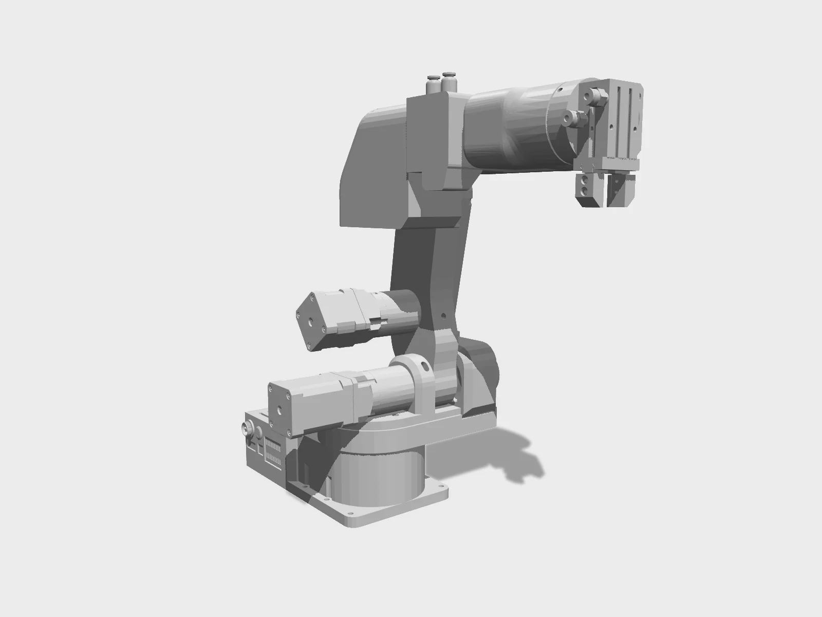
- Drawing
- /sourcerobotics/parol6
- Maker
- Source Robotics
- Country
- Zagreb, HR
- Package rev
- v0.1.0
- Level
- L1 Compiled
- Availability
- Kit
- Openness
- 90/100
- HW licence
- GPL-3.0
- Last checked
- 2026-09-25
- Mass
- 5.5 kg
- DOF
- 6
Repo moved from PCrnjak (Petar Crnjak) to the Source-Robotics org. Maker reports >250 units in use worldwide. URDF (ROS package with Gazebo launch) is in PAROL6_URDF/. STL files, BOM, firmware and PAROL Commander are GPL-3.0; per the assembly manual the STEP files and the PAROL6 control board are not open source, and the board is only sold by Source Robotics. No trained policies or datasets found on Hugging Face (2026-09-25).
Configure
Saved in the URL. Share the link to share the build.Source
One cart across 2 vendors · prices in USD as listedSource Robotics sells a kit. Buying from the maker funds the people who opened the design. No BOM line below lists them as a vendor yet, so check their store before ordering parts one by one.
63 lines · 376 parts · 42 without an offer in US · 22/63 lines sourced in 2+ regions (L3 gate)
| # | Part | Category | Qty | Unit | Line | Offer |
|---|---|---|---|---|---|---|
StepperOnline6 lines · unpriced | ||||||
| 1 | Stepper 1: NEMA 17, 16 Ncm, 42x42x20 mm, 1 A (J6 wrist) actuator.stepper1-17hs08-1004s · MPN 17HS08-1004S | actuator | 1 | unpriced | — | StepperOnlineships globallyLink from PAROL6 BOM.md |
| 2 | Stepper 2: NEMA 17, 45 Ncm, 42x42x40 mm, 2 A (J3, J4, J5) actuator.stepper2-17hs16-2004s1 · MPN 17HS16-2004S1 | actuator | 3 | unpriced | — | StepperOnlineships globallyLink from PAROL6 BOM.md |
| 3 | Stepper 3: NEMA 17, 65 Ncm, 42x42x60 mm, 2.1 A (J1, J2) actuator.stepper3-17hs24-2104s · MPN 17HS24-2104S | actuator | 2 | unpriced | — | StepperOnlineships globallyLink from PAROL6 BOM.md |
| 4 | EG-series precision planetary gearbox 20:1 for NEMA 17 (J2, J3) actuator.gearbox-eg17-g20 · MPN EG17-G20 · 1 alt | actuator | 2 | unpriced | — | StepperOnlineships globallyLink from PAROL6 BOM.md |
| 5 | EG-series precision planetary gearbox 10:1 for NEMA 17 (J6) actuator.gearbox-eg17-g10 · MPN EG17-G10 · 1 alt | actuator | 1 | unpriced | — | StepperOnlineships globallyLink from PAROL6 BOM.md |
| 6 | Power supply 24 V 5 A (BOM links Mean Well EDR-120-24, 120 W DIN rail, 115/230 VAC in) power.psu-24v-5a · MPN EDR-120-24 · 1 alt | power | 1 | unpriced | — | StepperOnlineships globallyLink from PAROL6 BOM.md |
Local / any hardware supplier15 lines · unpriced | ||||||
| 7 | M4x10 socket head cap screw, DIN 912 / ISO 4762 fastener.m4x10-shcs | fastener | 20 | unpriced | — | Local / any hardware supplierships globallyBOM.md: screws can be bought locally or from many vendors |
| 8 | M3x8 screw, 2 mm head height (bottom lid) fastener.m3x8-lowhead | fastener | 10 | unpriced | — | Local / any hardware supplierships globallyBOM.md: screws can be bought locally or from many vendors |
| 9 | M3x8 socket head cap screw, DIN 912 / ISO 4762 fastener.m3x8-shcs | fastener | 50 | unpriced | — | Local / any hardware supplierships globallyBOM.md: screws can be bought locally or from many vendors |
| 10 | M3x14 socket head cap screw, DIN 912 / ISO 4762 fastener.m3x14-shcs | fastener | 30 | unpriced | — | Local / any hardware supplierships globallyBOM.md: screws can be bought locally or from many vendors |
| 11 | M3 nut fastener.m3-nut | fastener | 10 | unpriced | — | Local / any hardware supplierships globallyBOM.md: nuts can be bought locally or from many vendors |
| 12 | M3x25 socket head cap screw, DIN 912 / ISO 4762 fastener.m3x25-shcs | fastener | 10 | unpriced | — | Local / any hardware supplierships globallyBOM.md: screws can be bought locally or from many vendors |
| 13 | M2x10 socket head cap screw, DIN 912 / ISO 4762 (limit switches) fastener.m2x10-shcs | fastener | 10 | unpriced | — | Local / any hardware supplierships globallyBOM.md: screws can be bought locally or from many vendors |
| 14 | M3x16 socket head cap screw, DIN 912 / ISO 4762 fastener.m3x16-shcs | fastener | 10 | unpriced | — | Local / any hardware supplierships globallyBOM.md: screws can be bought locally or from many vendors |
| 15 | M3x6 pan head Phillips screw (J4 homing trigger screw) fastener.m3x6-pan | fastener | 10 | unpriced | — | Local / any hardware supplierships globallyBOM.md: screws can be bought locally or from many vendors |
| 16 | M3x12 socket head cap screw, DIN 912 / ISO 4762 fastener.m3x12-shcs | fastener | 30 | unpriced | — | Local / any hardware supplierships globallyBOM.md: screws can be bought locally or from many vendors |
| 17 | M3x35 socket head cap screw, DIN 912 / ISO 4762 (manual allows 35 or 38 mm for the J3 pulley) fastener.m3x35-shcs | fastener | 10 | unpriced | — | Local / any hardware supplierships globallyBOM.md: screws can be bought locally or from many vendors |
| 18 | M4x16 socket head cap screw, DIN 912 / ISO 4762 fastener.m4x16-shcs | fastener | 30 | unpriced | — | Local / any hardware supplierships globallyBOM.md: screws can be bought locally or from many vendors |
| 19 | M4x14 socket head cap screw, DIN 912 / ISO 4762 (includes J1 homing screw) fastener.m4x14-shcs | fastener | 10 | unpriced | — | Local / any hardware supplierships globallyBOM.md: screws can be bought locally or from many vendors |
| 20 | M4x50 socket head cap screw, DIN 912 / ISO 4762 (J2 shaft) fastener.m4x50-shcs | fastener | 10 | unpriced | — | Local / any hardware supplierships globallyBOM.md: screws can be bought locally or from many vendors |
| 21 | M3x15 tapered (countersunk) head screw (J4 belt tension bearings) fastener.m3x15-tapered | fastener | 2 | unpriced | — | Local / any hardware supplierships globallyBOM.md: screws can be bought locally or from many vendors |
No offer in this region42 lines · unpriced | ||||||
| 22 | HTD 3M belt, 396 mm, 6 mm wide (J1) structure.belt-htd3m-396 | structure | 1 | unpriced | — | Offers in CN only |
| 23 | HTD 3M belt, 342 mm, 6 mm wide (J3) structure.belt-htd3m-342 | structure | 1 | unpriced | — | Offers in CN only |
| 24 | HTD 3M belt, 201 mm, 6 mm wide (J4) structure.belt-htd3m-201 | structure | 1 | unpriced | — | Offers in CN only |
| 25 | HTD 3M belt, 246 mm, 6 mm wide (J5) structure.belt-htd3m-246 | structure | 1 | unpriced | — | Offers in CN only |
| 26 | HTD 3M pulley, 12 tooth, 5 mm bore, 10 mm wide (J4, J5 motor pulleys) structure.pulley-htd3m-12t | structure | 2 | unpriced | — | Offers in CN only |
| 27 | HTD 3M pulley, 15 tooth, 5 mm bore, 10 mm wide (J1 motor pulley) structure.pulley-htd3m-15t | structure | 1 | unpriced | — | Offers in CN only |
| 28 | Flange shaft coupler, 8 mm bore, M4 screw holes (J2 shaft, J3 pulley, gripper) structure.shaft-coupler-8mm | structure | 3 | unpriced | — | Offers in CN only |
| 29 | Bearing 1: AXK3552 needle thrust bearing 35x52x4 with top and bottom washers (wrist) structure.bearing-axk3552 · MPN AXK3552 | structure | 1 | unpriced | — | Offers in CN only |
| 30 | Bearing 2: NSK HR32906J tapered roller bearing (J3, J4, J5) structure.bearing-hr32906j · MPN HR32906J | structure | 5 | unpriced | — | Offers in CN only |
| 31 | Bearing 3: NSK HR32907J tapered roller bearing (J1, J2) structure.bearing-hr32907j · MPN HR32907J | structure | 4 | unpriced | — | Offers in CN only |
| 32 | Ball bearing 3x8x4 mm (belt tensioners) structure.bearing-3x8x4 | structure | 20 | unpriced | — | Offers in CN only |
| 33 | Ball bearing 3x10x4 mm (belt tensioners) structure.bearing-3x10x4 | structure | 20 | unpriced | — | Offers in CN only |
| 34 | PAROL6 control board (STM32F446RE, 6x TMC5160 sockets, USB, CAN, 2 isolated in / 2 out) electronics.parol6-control-board | electronics | 1 | unpriced | — | Offers in EU only |
| 35 | TMC5160 stepper driver module (SPI) electronics.tmc5160-driver · MPN TMC5160 · 1 alt | electronics | 6 | unpriced | — | Offers in CN only |
| 36 | Thermal cement for driver heatsinks (only if the board came without drivers) electronics.thermal-cement | other | 2 | unpriced | — | Offers in CN only |
| 37 | On/off push button, 12 mm, 3-6 V electronics.power-button | electronics | 1 | unpriced | — | Offers in CN only |
| 38 | JST PH 2.0 mm 4-pin lead, 200 mm (power button, cut to 80 mm) cable.jst-ph-4pin | cable | 1 | unpriced | — | Offers in CN only |
| 39 | Noctua NF-A4x20 5V 40 mm fan (or any 40x40x20 mm 5 V non-PWM fan, <0.3 A) electronics.fan-40mm-5v · MPN NF-A4x20 5V | electronics | 1 | unpriced | — | No offer found yet |
| 40 | GX16 2-pin power connector, male + female cable.gx16-2pin | cable | 1 | unpriced | — | Offers in CN only |
| 41 | M8 4-pin female sensor connector (electric gripper / CAN port at J5) cable.m8-4pin-female | cable | 1 | unpriced | — | Offers in CN only |
| 42 | Limit switch, type ZW12-3 (J2, J3, J5) sensor.limit-switch-zw12-3 · MPN ZW12-3 | sensor | 3 | unpriced | — | Offers in CN only |
| 43 | Inductive sensor 1: 4 mm, NPN NO (J6 homing, 'Sensor 1') sensor.inductive-4mm | sensor | 1 | unpriced | — | Offers in CN only |
| 44 | Inductive sensor 2: GX-F8A (J4 homing, 'Sensor 2') sensor.inductive-gx-f8a · MPN GX-F8A | sensor | 1 | unpriced | — | Offers in CN only |
| 45 | Inductive sensor 3: M5, NPN NO (J1 homing, 'Sensor 3') sensor.inductive-m5 | sensor | 1 | unpriced | — | Offers in CN only |
| 46 | E-stop button, normally closed (any NC E-stop) electronics.estop-nc | electronics | 1 | unpriced | — | Offers in CN only |
| 47 | Cable gland PG7 (E-stop box) cable.gland-pg7 | cable | 1 | unpriced | — | Offers in CN only |
| 48 | M3 brass heat-set insert, 6 mm long (E-stop box) fastener.brass-insert-m3x6 | fastener | 4 | unpriced | — | Offers in CN only |
| 49 | XT30 female connector (power lead into the control board) cable.xt30-female | cable | 1 | unpriced | — | Offers in CN only |
| 50 | ST-Link / programming adapter (pin order SWCLK, SWDIO, GND, 3V3, 5V) electronics.stlink-adapter · 1 alt | electronics | 1 | unpriced | — | Offers in EU, CN only |
| 51 | USB-B cable (PC comms) cable.usb-b | cable | 1 | unpriced | — | No offer found yet |
| 52 | Pneumatic bulkhead connector, 4 mm, type PM (forearm + base) other.pneumatic-connector-pm4 | other | 4 | unpriced | — | Offers in CN only |
| 53 | Pneumatic parallel gripper MHZ2-16D other.pneumatic-gripper-mhz2-16d · MPN MHZ2-16D | other | 1 | unpriced | — | Offers in CN only |
| 54 | Pneumatic fitting PC4-M5 (gripper ports) other.pneumatic-fitting-pc4-m5 | other | 2 | unpriced | — | Offers in CN only |
| 55 | Pneumatic tube 4x2.5 mm (metres; BOM lists '5 meters') other.pneumatic-tube-4mm | other | 5 | unpriced | — | Offers in CN only |
| 56 | 5/2 solenoid air valve, 24 V, 4 mm tube connectors other.solenoid-valve-5-2 | other | 1 | unpriced | — | Offers in CN only |
| 57 | Suction cup gripper (optional vacuum gripper) other.vacuum-suction-cup | other | 1 | unpriced | — | Offers in CN only |
| 58 | Vacuum generator (optional vacuum gripper) other.vacuum-generator | other | 1 | unpriced | — | Offers in CN only |
| 59 | 4 mm to 6 mm tube coupler (optional vacuum gripper) other.coupler-4-6mm | other | 1 | unpriced | — | Offers in CN only |
| 60 | Dowel pin 4x18 mm, solid steel (small-bed split J1 turret only) fastener.dowel-4x18 | fastener | 3 | unpriced | — | Offers in CN only |
| 61 | Dowel pin 6x22 mm, solid steel (small-bed split upper arm only) fastener.dowel-6x22 | fastener | 4 | unpriced | — | Offers in CN only |
| 62 | Two-part epoxy, 1:1, slow setting (small-bed split parts only) other.epoxy-2-part | other | 1 | unpriced | — | Offers in CN only |
| 63 | Consumables: blue threadlocker, lithium grease, insulation tape, solder, heat shrink, wire harness, cloth fabric tape other.consumables | other | 1 | unpriced | — | No offer found yet |
| Cart total · US | 376 | $0.00 | 63 lines unpriced, not in total | |||
Fabricate
Planned for a 256 mm bed- Fabricated parts
- 41
- Print time (sum)
- 95 h
- Material (sum)
- 1,158 g
- Plates · estimate
- ≈ 6
Plates is an estimate, not a slice: the package has no part footprints, so it assumes about 200 g of FDM parts per plate on a 256 mm bed, scaled by bed area (256 mm ≈ 200 g/plate). Parts larger than your bed are not detected. One printer running around the clock: about 4.0 days.
| Part | Process | Material | Qty | h / part | g / part | Profile |
|---|---|---|---|---|---|---|
Electronics_case_v1_1 printed.electronics-case | FDM | PETG | 1 | — | — | PETG, 0.2 mm layers, honeycomb infill, 3 perimeters, 6 top / 4 bottom layers, 15% part cooling; 50% infill; supports: minimal; listed as Electronics_case (upstream print table) |
lid_electronics printed.lid-electronics | FDM | PETG | 1 | — | — | PETG, 0.2 mm layers, honeycomb infill, 3 perimeters, 6 top / 4 bottom layers, 15% part cooling; no exact row in the print table (closest: Electronics_cover, 20% infill, minimal supports, 80 g, 6 h) |
fan_cover printed.fan-cover | FDM | PETG | 1 | — | — | PETG, 0.2 mm layers, honeycomb infill, 3 perimeters, 6 top / 4 bottom layers, 15% part cooling; 20% infill; supports: minimal (upstream print table) |
J1_bottom_lid printed.j1-bottom-lid | FDM | PETG | 1 | — | — | PETG, 0.2 mm layers, honeycomb infill, 3 perimeters, 6 top / 4 bottom layers, 15% part cooling; 25% infill; supports: minimal (upstream print table) |
main_base_blocker (Main_base in the manual and print table) printed.main-base | FDM | PETG | 1 | — | — | PETG, 0.2 mm layers, honeycomb infill, 3 perimeters, 6 top / 4 bottom layers, 15% part cooling; 50% infill; supports: minimal (upstream print table) |
J1_turret_rework_blocker (J1_turret with J1 stopper rails) printed.j1-turret | FDM | PETG | 1 | 18.0 | 210 | PETG, 0.2 mm layers, honeycomb infill, 3 perimeters, 6 top / 4 bottom layers, 15% part cooling; 25% infill; supports: minimal; a second table row lists J1_turret at 45%; needs a bed of about 175 mm, see small-bed split (upstream print table) |
J1_turret_motor_holder printed.j1-turret-motor-holder | FDM | PETG | 1 | 6.0 | 53 | PETG, 0.2 mm layers, honeycomb infill, 3 perimeters, 6 top / 4 bottom layers, 15% part cooling; 80% infill; supports: minimal (upstream print table) |
J1_rotation_shaft printed.j1-rotation-shaft | FDM | PETG | 1 | 3.6 | 31 | PETG, 0.2 mm layers, honeycomb infill, 3 perimeters, 6 top / 4 bottom layers, 15% part cooling; 50% infill; supports: none (upstream print table) |
J1_backplate printed.j1-backplate | FDM | PETG | 1 | — | — | PETG, 0.2 mm layers, honeycomb infill, 3 perimeters, 6 top / 4 bottom layers, 15% part cooling; 50% infill; supports: minimal (upstream print table) |
J1_belt_cover_rework printed.j1-belt-cover | FDM | PETG | 1 | 2.0 | 37 | PETG, 0.2 mm layers, honeycomb infill, 3 perimeters, 6 top / 4 bottom layers, 15% part cooling; 20% infill; supports: none; listed as J1_belt_cover (upstream print table) |
J1_wires_cover_rework printed.j1-wires-cover | FDM | PETG | 1 | — | — | PETG, 0.2 mm layers, honeycomb infill, 3 perimeters, 6 top / 4 bottom layers, 15% part cooling; not in the print table |
J2_limit_switch_cover printed.j2-limit-switch-cover | FDM | PETG | 1 | 0.2 | 3 | PETG, 0.2 mm layers, honeycomb infill, 3 perimeters, 6 top / 4 bottom layers, 15% part cooling; 25% infill; supports: minimal; a second row lists 50% (upstream print table) |
J2_stopper_block printed.j2-stopper-block | FDM | PETG | 1 | — | — | PETG, 0.2 mm layers, honeycomb infill, 3 perimeters, 6 top / 4 bottom layers, 15% part cooling; no exact row (table has J2_stepper_blocker 20% and J1_stepper_block 45%) |
Upper_arm printed.upper-arm | FDM | PETG | 1 | 18.0 | 220 | PETG, 0.2 mm layers, honeycomb infill, 3 perimeters, 6 top / 4 bottom layers, 15% part cooling; 35% infill; supports: minimal; needs a bed of about 175 mm, see small-bed split (upstream print table) |
Upper_arm_cover printed.upper-arm-cover | FDM | PETG | 1 | 2.0 | 34 | PETG, 0.2 mm layers, honeycomb infill, 3 perimeters, 6 top / 4 bottom layers, 15% part cooling; 15% infill; supports: minimal (upstream print table) |
Upper_arm_wires_cover printed.upper-arm-wires-cover | FDM | PETG | 1 | — | — | PETG, 0.2 mm layers, honeycomb infill, 3 perimeters, 6 top / 4 bottom layers, 15% part cooling; 45% infill; supports: minimal (upstream print table) |
J2_shaft printed.j2-shaft | FDM | PETG | 1 | 4.7 | 43 | PETG, 0.2 mm layers, honeycomb infill, 3 perimeters, 6 top / 4 bottom layers, 15% part cooling; 50% infill; supports: none (upstream print table) |
J2_cover printed.j2-cover | FDM | PETG | 1 | 0.7 | 10 | PETG, 0.2 mm layers, honeycomb infill, 3 perimeters, 6 top / 4 bottom layers, 15% part cooling; 20% infill; supports: none (upstream print table) |
J2_bearing_backplate printed.j2-bearing-backplate | FDM | PETG | 1 | 0.7 | 10 | PETG, 0.2 mm layers, honeycomb infill, 3 perimeters, 6 top / 4 bottom layers, 15% part cooling; 20% infill; supports: none (upstream print table) |
J3_limit_switch_cover printed.j3-limit-switch-cover | FDM | PETG | 1 | 0.4 | 4 | PETG, 0.2 mm layers, honeycomb infill, 3 perimeters, 6 top / 4 bottom layers, 15% part cooling; 50% infill; supports: none (upstream print table) |
38_pulley_J3 (J3 output pulley) printed.pulley-38-j3 | FDM | PETG | 1 | — | — | PETG, 0.2 mm layers, honeycomb infill, 3 perimeters, 6 top / 4 bottom layers, 15% part cooling; 70% infill; supports: minimal (upstream print table) |
42_pulley (J3 input pulley on the gearbox shaft coupler) printed.pulley-42 | FDM | PETG | 1 | — | — | PETG, 0.2 mm layers, honeycomb infill, 3 perimeters, 6 top / 4 bottom layers, 15% part cooling; 70% infill; supports: minimal (upstream print table) |
Elbow_part printed.elbow-part | FDM | PETG | 1 | 16.0 | 215 | PETG, 0.2 mm layers, honeycomb infill, 3 perimeters, 6 top / 4 bottom layers, 15% part cooling; 25% infill; supports: a lot (upstream print table) |
Elbow_lid_1 printed.elbow-lid-1 | FDM | PETG | 1 | 1.8 | 20 | PETG, 0.2 mm layers, honeycomb infill, 3 perimeters, 6 top / 4 bottom layers, 15% part cooling; 20% infill; supports: none (upstream print table) |
Elbow_lid_2 printed.elbow-lid-2 | FDM | PETG | 1 | 0.3 | 4 | PETG, 0.2 mm layers, honeycomb infill, 3 perimeters, 6 top / 4 bottom layers, 15% part cooling; 20% infill; supports: none (upstream print table) |
J4_bearing_backplate printed.j4-bearing-backplate | FDM | PETG | 1 | — | — | PETG, 0.2 mm layers, honeycomb infill, 3 perimeters, 6 top / 4 bottom layers, 15% part cooling; supports none; infill not given in the print table |
J4_limiter printed.j4-limiter | FDM | PETG | 1 | — | 1 | PETG, 0.2 mm layers, honeycomb infill, 3 perimeters, 6 top / 4 bottom layers, 15% part cooling; 80% infill; supports: none; about 2 min (upstream print table) |
J5_part (forearm body) printed.j5-part | FDM | PETG | 1 | 10.0 | 114 | PETG, 0.2 mm layers, honeycomb infill, 3 perimeters, 6 top / 4 bottom layers, 15% part cooling; 30% infill; supports: minimal (upstream print table) |
J5_belt_lid printed.j5-belt-lid | FDM | PETG | 1 | — | 20 | PETG, 0.2 mm layers, honeycomb infill, 3 perimeters, 6 top / 4 bottom layers, 15% part cooling; 15% infill; supports: none (upstream print table) |
J5_electronics_lid printed.j5-electronics-lid | FDM | PETG | 1 | — | 20 | PETG, 0.2 mm layers, honeycomb infill, 3 perimeters, 6 top / 4 bottom layers, 15% part cooling; 15% infill; supports: none (upstream print table) |
HTD3_48_J5_pulley (48 tooth J5 output pulley) printed.htd3-48-j5-pulley | FDM | PETG | 1 | — | — | PETG, 0.2 mm layers, honeycomb infill, 3 perimeters, 6 top / 4 bottom layers, 15% part cooling; 60% infill; supports: minimal; an older 'J5 pulley' row gives 40%, 20 g, 2 h (upstream print table) |
J4_output_pulley printed.j4-output-pulley | FDM | PETG | 1 | — | — | PETG, 0.2 mm layers, honeycomb infill, 3 perimeters, 6 top / 4 bottom layers, 15% part cooling; 50% infill; supports: minimal (upstream print table) |
wrist (J6 housing) printed.wrist | FDM | PETG | 1 | 7.9 | 78 | PETG, 0.2 mm layers, honeycomb infill, 3 perimeters, 6 top / 4 bottom layers, 15% part cooling; 40% infill; supports: minimal (upstream print table) |
Pneumatic_gripper_holder printed.pneumatic-gripper-holder | FDM | PETG | 1 | 2.9 | 31 | PETG, 0.2 mm layers, honeycomb infill, 3 perimeters, 6 top / 4 bottom layers, 15% part cooling; 40% infill; supports: none; a second row gives 30% with minimal supports (upstream print table) |
Gripper_ARMS (jaws for the pneumatic gripper; print count not stated) printed.gripper-arms | FDM | PETG | 1 | — | — | PETG, 0.2 mm layers, honeycomb infill, 3 perimeters, 6 top / 4 bottom layers, 15% part cooling; not in the print table |
vacuum_gripper_holder (optional vacuum gripper) printed.vacuum-gripper-holder | FDM | PETG | 1 | — | — | PETG, 0.2 mm layers, honeycomb infill, 3 perimeters, 6 top / 4 bottom layers, 15% part cooling; not in the print table |
ESTOP_TOP printed.estop-top | FDM | PETG | 1 | — | — | PETG, 0.2 mm layers, honeycomb infill, 3 perimeters, 6 top / 4 bottom layers, 15% part cooling; not in the print table |
ESTOP_BOTTOM printed.estop-bottom | FDM | PETG | 1 | — | — | PETG, 0.2 mm layers, honeycomb infill, 3 perimeters, 6 top / 4 bottom layers, 15% part cooling; not in the print table |
connectors_4_alu_profiles (optional 30x30 profile base; needs M5 T-nuts and M5 screws) printed.alu-profile-connector | FDM | PETG | 1 | — | — | PETG, 0.2 mm layers, honeycomb infill, 3 perimeters, 6 top / 4 bottom layers, 15% part cooling; not in the print table |
Upper_arm_A_long_end + Upper_arm_B_short_end (replaces Upper_arm on beds under ~175 mm) printed.small-bed-upper-arm | FDM | PETG | 1 | — | — | Optional two-piece replacement joined with 6x22 dowels and epoxy; ream per the small print bed PDF |
J1_turret_rework_blocker_A_turret_end + _B_arm_end (replaces J1 turret on small beds) printed.small-bed-j1-turret | FDM | PETG | 1 | — | — | Optional two-piece replacement joined with 4x18 dowels and epoxy; ream per the small print bed PDF |
Assemble
Every step ends in a check- Steps
- 25
- Subassemblies
- 7
- Hands-on time (sum)
- —
- Critical path
- —
- Your progress · this device
- —
25 steps have no time estimate; times above are lower bounds.
Steps, in build order
- Fabrication01
Print all parts in PETG
Print every part in PETG (the manual requires PETG; upstream prints on a Prusa MK2S). Use the print table for infill and supports: 0.2 mm layers, honeycomb infill, 3 perimeters, 6 top / 4 bottom layers, 15% cooling. PETG: 220-250 °C hotend, 60-90 °C bed, part fan on. Remove all support material. Screws thread directly into undersized printed holes; if a thread strips later, fill with super glue and re-tap.
CHECKEvery STL in STL/BASE, SHOULDER, UPPER_ARM, ELBOW, FOREARM, WRIST, ESTOP and GRIPPER_ATTACHMENTS is printed, support-free, and bearing seats accept the tapered bearings without cracking.- Parts in
- Electronics_case_v1_1printed.electronics-case
- lid_electronicsprinted.lid-electronics
- fan_coverprinted.fan-cover
- J1_bottom_lidprinted.j1-bottom-lid
- main_base_blocker (Main_base in the manual and print table)printed.main-base
- J1_turret_rework_blocker (J1_turret with J1 stopper rails)printed.j1-turret
- J1_turret_motor_holderprinted.j1-turret-motor-holder
- J1_rotation_shaftprinted.j1-rotation-shaft
- J1_backplateprinted.j1-backplate
- J1_belt_cover_reworkprinted.j1-belt-cover
- J1_wires_cover_reworkprinted.j1-wires-cover
- J2_limit_switch_coverprinted.j2-limit-switch-cover
- J2_stopper_blockprinted.j2-stopper-block
- Upper_armprinted.upper-arm
- Upper_arm_coverprinted.upper-arm-cover
- Upper_arm_wires_coverprinted.upper-arm-wires-cover
- J2_shaftprinted.j2-shaft
- J2_coverprinted.j2-cover
- J2_bearing_backplateprinted.j2-bearing-backplate
- J3_limit_switch_coverprinted.j3-limit-switch-cover
- 38_pulley_J3 (J3 output pulley)printed.pulley-38-j3
- 42_pulley (J3 input pulley on the gearbox shaft coupler)printed.pulley-42
- Elbow_partprinted.elbow-part
- Elbow_lid_1printed.elbow-lid-1
- Elbow_lid_2printed.elbow-lid-2
- J4_bearing_backplateprinted.j4-bearing-backplate
- J4_limiterprinted.j4-limiter
- J5_part (forearm body)printed.j5-part
- J5_belt_lidprinted.j5-belt-lid
- J5_electronics_lidprinted.j5-electronics-lid
- HTD3_48_J5_pulley (48 tooth J5 output pulley)printed.htd3-48-j5-pulley
- J4_output_pulleyprinted.j4-output-pulley
- wrist (J6 housing)printed.wrist
- Pneumatic_gripper_holderprinted.pneumatic-gripper-holder
- Gripper_ARMS (jaws for the pneumatic gripper; print count not stated)printed.gripper-arms
- ESTOP_TOPprinted.estop-top
- ESTOP_BOTTOMprinted.estop-bottom
- Tools
- FDM printer, about 175 mm bed for Upper_arm and J1 turret (or use the SMALL_PRINT_BED split parts)
- Torque
- —
- Time
- —
- After
- Start
- Source
- github.com
- 02
Optional: join split parts for small print beds
Only if Upper_arm or J1_turret_rework_blocker does not fit your bed (smallest bounding cube 160.5 mm and 154.1 mm). Print both halves, ream the dowel holes, and join the upper arm with 4 steel 6x22 mm dowels and the J1 turret with 3 steel 4x18 mm dowels plus slow-setting 1:1 epoxy, following the small print bed PDF. A one-piece print is always stronger.
CHECKAfter the epoxy cures, the joined part has no step at the seam and does not flex at the joint when loaded by hand.- Parts in
- Upper_arm_A_long_end + Upper_arm_B_short_end (replaces Upper_arm on beds under ~175 mm)printed.small-bed-upper-arm
- J1_turret_rework_blocker_A_turret_end + _B_arm_end (replaces J1 turret on small beds)printed.small-bed-j1-turret
- Dowel pin 6x22 mm, solid steel (small-bed split upper arm only)fastener.dowel-6x22
- Dowel pin 4x18 mm, solid steel (small-bed split J1 turret only)fastener.dowel-4x18
- Two-part epoxy, 1:1, slow setting (small-bed split parts only)other.epoxy-2-part
- Tools
- Reamers per the small print bed PDF, Clamps
- Torque
- —
- Time
- —
- After
- Start
- Source
- github.com
- 03
Prepare limit switches with 1 m leads
Solder 1 m wires to the contacts marked on page 16 of the manual on all three ZW12-3 switches and cover each joint with heat shrink. Mark every wire as you go; almost all wiring runs inside the arm and is hard to identify later.
CHECKEach switch reads open/closed across its 1 m leads on a multimeter as the lever is pressed.- Parts in
- Limit switch, type ZW12-3 (J2, J3, J5)sensor.limit-switch-zw12-3
- Consumables: blue threadlocker, lithium grease, insulation tape, solder, heat shrink, wire harness, cloth fabric tapeother.consumables
- Tools
- Soldering iron, Heat gun
- Torque
- —
- Time
- —
- After
- Start
- Source
- github.com
- Arm assembly04
Wrist: J6 motor, 10:1 gearbox, homing sensor
Build from the wrist toward the base; the manual states any other order will not work because all wires pass through the arm. Couple Stepper 1 to the 10:1 gearbox with the gearbox's own coupler (tighten both set screws through the side holes; motor-to-gearbox screws are the ones supplied with the gearbox). Mount it in the wrist (3x M4x10, 4x M3x8) with the orientation shown. Press-fit Sensor 1 (4 mm inductive) flat against the top of the wrist; use an M3x14 and M3 nut if it is loose. Route motor and sensor wires out of the marked hole, then attach the AXK3552 bearing.
CHECKSensor 1 sits flush and does not move when pushed; the gearbox output turns smoothly by hand with no coupler slip.- Parts in
- wrist (J6 housing)printed.wrist
- Stepper 1: NEMA 17, 16 Ncm, 42x42x20 mm, 1 A (J6 wrist)actuator.stepper1-17hs08-1004s
- EG-series precision planetary gearbox 10:1 for NEMA 17 (J6)actuator.gearbox-eg17-g10
- Inductive sensor 1: 4 mm, NPN NO (J6 homing, 'Sensor 1')sensor.inductive-4mm
- Bearing 1: AXK3552 needle thrust bearing 35x52x4 with top and bottom washers (wrist)structure.bearing-axk3552
- M4x10 socket head cap screw, DIN 912 / ISO 4762fastener.m4x10-shcs
- M3x8 socket head cap screw, DIN 912 / ISO 4762fastener.m3x8-shcs
- M3x14 socket head cap screw, DIN 912 / ISO 4762fastener.m3x14-shcs
- M3 nutfastener.m3-nut
- Tools
- Hex key set, Torque screwdriver
- Torque
- —
- Time
- —
- Source
- github.com
- 05
Shoulder: J2 motor, gearbox and shaft coupler
Couple a Stepper 3 to the second 20:1 gearbox (4x M3x8), then fix J1_turret_motor_holder to the gearbox (4x M4x16) with the stepper wires positioned as shown. Mount the 8 mm shaft coupler (4x M4x16) with its set-screw hole aligned as marked. No key is used: drive the coupler set screw into the gearbox keyway with blue threadlocker and let it cure a few hours.
CHECKThe coupler set screw sits in the keyway and the coupler does not slip on the shaft when twisted hard by hand after curing.- Parts in
- J1_turret_motor_holderprinted.j1-turret-motor-holder
- Stepper 3: NEMA 17, 65 Ncm, 42x42x60 mm, 2.1 A (J1, J2)actuator.stepper3-17hs24-2104s
- EG-series precision planetary gearbox 20:1 for NEMA 17 (J2, J3)actuator.gearbox-eg17-g20
- Flange shaft coupler, 8 mm bore, M4 screw holes (J2 shaft, J3 pulley, gripper)structure.shaft-coupler-8mm
- M3x8 socket head cap screw, DIN 912 / ISO 4762fastener.m3x8-shcs
- M4x16 socket head cap screw, DIN 912 / ISO 4762fastener.m4x16-shcs
- Consumables: blue threadlocker, lithium grease, insulation tape, solder, heat shrink, wire harness, cloth fabric tapeother.consumables
- Tools
- —
- Torque
- —
- Time
- —
- After
- 01
- Source
- github.com
- Electronics06
Bench-test the control board with the test firmware
Safety · human-verified requiredIf your board has no drivers: remove the two DIAG pins from each TMC5160 and cement the heatsinks with thermal cement. Insert all six drivers with the DIAG pins at the red arrows in the docs; a reversed driver permanently destroys the board. With 24 V disconnected, connect only USB and the programming adapter (SWCLK, SWDIO, GND, 3V3 only; an ST-Link cable without the adapter destroys the board) and upload the PlatformIO project in 'PAROL6 control board test code' (env genericSTM32F446RE, upload_protocol stlink, e.g. `pio run -e genericSTM32F446RE -t upload`). Use it only on individual components, never on an assembled arm, since it spins every motor. Then remove the adapter, connect 24 V and hold the power button. Type `# LIMIT` and `# IO` in the serial terminal.
CHECKThe serial monitor reports all six drivers without errors, OUT1/OUT2 toggle every 1 s with LED1/LED2 flashing, a bench motor turns slowly at 200-300 mA, `# LIMIT` shows a switch changing state and `# IO` shows the supply voltage in mV.This step can hurt a person or ruin parts. Its instructions need sign-off by a human who has done it before relying on them. Stop and ask if anything differs from what you see.
- Parts in
- PAROL6 control board (STM32F446RE, 6x TMC5160 sockets, USB, CAN, 2 isolated in / 2 out)electronics.parol6-control-board
- TMC5160 stepper driver module (SPI)electronics.tmc5160-driver
- Thermal cement for driver heatsinks (only if the board came without drivers)electronics.thermal-cement
- ST-Link / programming adapter (pin order SWCLK, SWDIO, GND, 3V3, 5V)electronics.stlink-adapter
- USB-B cable (PC comms)cable.usb-b
- Tools
- ST-Link V2 + PAROL6 programming adapter, PlatformIO (VS Code), Serial terminal
- Torque
- —
- Time
- —
- After
- 01
- Arm assembly07
Forearm: J5 bearing, 48T pulley, J5 motor, limit switch, gripper port
Seat a HR32906J in the J5_part groove, tapping evenly around the whole race with a rubber hammer (or a screwdriver and light hammer taps). Pull all J6 wires through HTD3_48_J5_pulley and the bearing. Mount the J5 Stepper 2 flipped 180° from the manual image so its wires exit through the J5_part hole (4x M3x14, 4x M3x25). Fix the limit switch with 2x M2x10 and two pneumatic connectors with their nuts. Solder 1 m leads to the M8 gripper connector, pinout 1 = 24 V, 2 = CANH, 3 = GND, 4 = CANL, with CANH/CANL as a twisted pair, and fit it in J5_electronics_lid (4x M3x8).
CHECKJ5 moves only within the limits shown on page 35 and never makes a full turn; M8 pins 2 and 4 ring through to the twisted pair at the far end.- Parts in
- J5_part (forearm body)printed.j5-part
- HTD3_48_J5_pulley (48 tooth J5 output pulley)printed.htd3-48-j5-pulley
- J5_electronics_lidprinted.j5-electronics-lid
- Bearing 2: NSK HR32906J tapered roller bearing (J3, J4, J5)structure.bearing-hr32906j
- Stepper 2: NEMA 17, 45 Ncm, 42x42x40 mm, 2 A (J3, J4, J5)actuator.stepper2-17hs16-2004s1
- Limit switch, type ZW12-3 (J2, J3, J5)sensor.limit-switch-zw12-3
- Pneumatic bulkhead connector, 4 mm, type PM (forearm + base)other.pneumatic-connector-pm4
- M8 4-pin female sensor connector (electric gripper / CAN port at J5)cable.m8-4pin-female
- M3x14 socket head cap screw, DIN 912 / ISO 4762fastener.m3x14-shcs
- M3x25 socket head cap screw, DIN 912 / ISO 4762fastener.m3x25-shcs
- M2x10 socket head cap screw, DIN 912 / ISO 4762 (limit switches)fastener.m2x10-shcs
- M3x8 socket head cap screw, DIN 912 / ISO 4762fastener.m3x8-shcs
- Tools
- Rubber hammer, Soldering iron
- Torque
- —
- Time
- —
- After
- 04
- Source
- github.com
- Electronics08
Wire the 24 V supply and GX16 power lead
Safety · human-verified requiredThe BOM supply (Mean Well EDR-120-24) is an open-terminal DIN-rail unit on 115/230 VAC; the upstream safety document warns of lethal voltages. Mount it in a closed, earthed enclosure, wire L, N and PE with the plug removed, and set the output to 24 V. Solder the GX16 2-pin male connector to the XT30 female with at least 110 mm of wire, following the polarity image in the manual exactly. The board accepts 18 V minimum, 24 V maximum.
CHECKWith mains applied and the lead unplugged from the robot, the GX16 socket reads +24 V (within ±0.5 V) with the correct polarity, and the PSU case reads 0 Ω to mains earth.This step can hurt a person or ruin parts. Its instructions need sign-off by a human who has done it before relying on them. Stop and ask if anything differs from what you see.
- Parts in
- Power supply 24 V 5 A (BOM links Mean Well EDR-120-24, 120 W DIN rail, 115/230 VAC in)power.psu-24v-5a
- GX16 2-pin power connector, male + femalecable.gx16-2pin
- XT30 female connector (power lead into the control board)cable.xt30-female
- Tools
- Multimeter, Soldering iron, Insulated screwdriver
- Torque
- —
- Time
- —
- After
- 06
- Source
- github.com
- Arm assembly09
J4 output pulley and J4 homing screw
Pass every wire and tube through J4_output_pulley and fix it to the lower arm with 6x M3x16. Fit the supplied M3x6 screw as the J4 sensor trigger; the manual warns a different screw triggers at the wrong position and corrupts the kinematics.
CHECKAll wires and both tubes exit through the pulley bore and the M3x6 trigger head stands proud at the marked hole.- Parts in
- J4_output_pulleyprinted.j4-output-pulley
- M3x16 socket head cap screw, DIN 912 / ISO 4762fastener.m3x16-shcs
- M3x6 pan head Phillips screw (J4 homing trigger screw)fastener.m3x6-pan
- Tools
- —
- Torque
- —
- Time
- —
- After
- 07
- Source
- github.com
- 10
Elbow: J4 bearings, motor, Sensor 2, J4 belt
Press two HR32906J into Elbow_part. Fix the J4 Stepper 2 with 4x M3x14, all wires through hole 2. Mount Sensor 2 (GX-F8A) and J4_limiter (M3x12, M3x8). Pull all wires and tubes through the elbow, then fit the 12T pulley and HTD3 201 belt with the pulleys in the illustrated position. Tension with paired 3x8x4 / 3x10x4 bearings on M3x15 tapered-head screws at the marked spots. Close with J4_bearing_backplate, Elbow_lid_2 (M3x14, 2x M3x8, 4x M3x14) and Elbow_lid_1 (4x M3x8).
CHECKJ4 and J5 move through their range by hand with no tight spots; if one binds, check bearing alignment, bearing-retainer screw torque and tangled wires (page 47).- Parts in
- Elbow_partprinted.elbow-part
- J4_limiterprinted.j4-limiter
- J4_bearing_backplateprinted.j4-bearing-backplate
- Elbow_lid_1printed.elbow-lid-1
- Elbow_lid_2printed.elbow-lid-2
- Bearing 2: NSK HR32906J tapered roller bearing (J3, J4, J5)structure.bearing-hr32906j
- Stepper 2: NEMA 17, 45 Ncm, 42x42x40 mm, 2 A (J3, J4, J5)actuator.stepper2-17hs16-2004s1
- Inductive sensor 2: GX-F8A (J4 homing, 'Sensor 2')sensor.inductive-gx-f8a
- HTD 3M pulley, 12 tooth, 5 mm bore, 10 mm wide (J4, J5 motor pulleys)structure.pulley-htd3m-12t
- HTD 3M belt, 201 mm, 6 mm wide (J4)structure.belt-htd3m-201
- Ball bearing 3x8x4 mm (belt tensioners)structure.bearing-3x8x4
- Ball bearing 3x10x4 mm (belt tensioners)structure.bearing-3x10x4
- M3x15 tapered (countersunk) head screw (J4 belt tension bearings)fastener.m3x15-tapered
- M3x14 socket head cap screw, DIN 912 / ISO 4762fastener.m3x14-shcs
- M3x12 socket head cap screw, DIN 912 / ISO 4762fastener.m3x12-shcs
- M3x8 socket head cap screw, DIN 912 / ISO 4762fastener.m3x8-shcs
- Tools
- Rubber hammer, Hex key set
- Torque
- —
- Time
- —
- After
- 09
- Source
- github.com
- 11
Upper arm: J3 bearings, J3 motor with 20:1 gearbox, J3 limit switch
Press two HR32906J into Upper_arm, fix 38_pulley_J3 with 6x M3x35 (or M3x38). Couple the J3 Stepper 2 to a 20:1 gearbox (4x M3x8) and mount it (4x M4x16) with the wire side as marked. Fit the J3 limit switch (2x M2x10) under J3_limit_switch_cover (3x M3x8). Join the upper arm to the forearm, wrap the harness in cloth tape, route it through hole 1 into slot 2 along the blue line (J3 switch and motor wires through the same slot), and close Upper_arm_wires_cover with 4x M3x12, pulling the wires tight. The J3 belt goes on later.
CHECKWith the wires enclosed, J3 moves through its range by hand without the harness pulling.- Parts in
- Upper_armprinted.upper-arm
- 38_pulley_J3 (J3 output pulley)printed.pulley-38-j3
- J3_limit_switch_coverprinted.j3-limit-switch-cover
- Upper_arm_wires_coverprinted.upper-arm-wires-cover
- Bearing 2: NSK HR32906J tapered roller bearing (J3, J4, J5)structure.bearing-hr32906j
- Stepper 2: NEMA 17, 45 Ncm, 42x42x40 mm, 2 A (J3, J4, J5)actuator.stepper2-17hs16-2004s1
- EG-series precision planetary gearbox 20:1 for NEMA 17 (J2, J3)actuator.gearbox-eg17-g20
- Limit switch, type ZW12-3 (J2, J3, J5)sensor.limit-switch-zw12-3
- M3x35 socket head cap screw, DIN 912 / ISO 4762 (manual allows 35 or 38 mm for the J3 pulley)fastener.m3x35-shcs
- M3x8 socket head cap screw, DIN 912 / ISO 4762fastener.m3x8-shcs
- M4x16 socket head cap screw, DIN 912 / ISO 4762fastener.m4x16-shcs
- M2x10 socket head cap screw, DIN 912 / ISO 4762 (limit switches)fastener.m2x10-shcs
- M3x12 socket head cap screw, DIN 912 / ISO 4762fastener.m3x12-shcs
- Consumables: blue threadlocker, lithium grease, insulation tape, solder, heat shrink, wire harness, cloth fabric tapeother.consumables
- Tools
- —
- Torque
- —
- Time
- —
- After
- 10
- Source
- github.com
- 12
Shoulder: J1 turret, rotation shaft, J2 bearings, shaft and covers
Join J1_turret and J1_rotation_shaft (6x M4x16). Screw in the M4x14 J1 homing screw so it just peeks out underneath; do not bottom it. Fit the J1 Stepper 3, the J2 limit switch (2x M2x10) under J2_limit_switch_cover (2x M3x8, 4x M3x14) and pull its wires down the rotation shaft. Add J2_stopper_block (M3x8, 2x M3x12), press two HR32907J, fit the upper arm on J2_shaft with 4x M4x50, then J2_bearing_backplate and J2_cover (4x M3x12, threaded parts). Feed the J1 motor wires through J1_belt_cover (not screwed yet), fit J1_wires_cover with 2x M2x10, then pull every remaining wire down the J1 rotation shaft.
CHECKJ2 swings through its range by hand, the J2 stopper stops it before the limit switch is crushed, and all harness ends hang out of the bottom of the J1 rotation shaft.- Parts in
- J1_turret_rework_blocker (J1_turret with J1 stopper rails)printed.j1-turret
- J1_rotation_shaftprinted.j1-rotation-shaft
- J2_limit_switch_coverprinted.j2-limit-switch-cover
- J2_stopper_blockprinted.j2-stopper-block
- J2_shaftprinted.j2-shaft
- J2_bearing_backplateprinted.j2-bearing-backplate
- J2_coverprinted.j2-cover
- J1_belt_cover_reworkprinted.j1-belt-cover
- J1_wires_cover_reworkprinted.j1-wires-cover
- Stepper 3: NEMA 17, 65 Ncm, 42x42x60 mm, 2.1 A (J1, J2)actuator.stepper3-17hs24-2104s
- Limit switch, type ZW12-3 (J2, J3, J5)sensor.limit-switch-zw12-3
- Bearing 3: NSK HR32907J tapered roller bearing (J1, J2)structure.bearing-hr32907j
- M4x16 socket head cap screw, DIN 912 / ISO 4762fastener.m4x16-shcs
- M4x14 socket head cap screw, DIN 912 / ISO 4762 (includes J1 homing screw)fastener.m4x14-shcs
- M3x8 socket head cap screw, DIN 912 / ISO 4762fastener.m3x8-shcs
- M3x14 socket head cap screw, DIN 912 / ISO 4762fastener.m3x14-shcs
- M3x12 socket head cap screw, DIN 912 / ISO 4762fastener.m3x12-shcs
- M2x10 socket head cap screw, DIN 912 / ISO 4762 (limit switches)fastener.m2x10-shcs
- M4x50 socket head cap screw, DIN 912 / ISO 4762 (J2 shaft)fastener.m4x50-shcs
- Tools
- —
- Torque
- —
- Time
- —
- Source
- github.com
- 13
Base: J1 bearings, Sensor 3, rotation limiter, J1 belt, backplate
Press two HR32907J into Main_base. Fit Sensor 3 (M5 inductive) level with the base using its two nuts. Screw an M3x20 fully into the marked hole as the J1 rotation limiter (the manual warns that without it J1 can do more than one turn and damage the robot). Loop the HTD3 396 belt, pull all wires except the J1 sensor through the base, slide the base up onto the J1 rotation shaft, then fit the covers and the 15T pulley (set screws through the cover holes). Add a tension bearing if needed. Fit J1_backplate with 6x M4x16 and route the harness: hole 1 = J1, J3, J5 steppers and limits 2, 1, 5; hole 2 = J2, J4, J6 steppers, limits 6, 3, 4, CAN and the pneumatic tubes.
CHECKJ1 turns by hand and is stopped by the M3x20 limiter before one full revolution; the J1 homing screw passes over Sensor 3 without touching it.- Parts in
- main_base_blocker (Main_base in the manual and print table)printed.main-base
- J1_backplateprinted.j1-backplate
- J1_belt_cover_reworkprinted.j1-belt-cover
- Bearing 3: NSK HR32907J tapered roller bearing (J1, J2)structure.bearing-hr32907j
- Inductive sensor 3: M5, NPN NO (J1 homing, 'Sensor 3')sensor.inductive-m5
- HTD 3M pulley, 15 tooth, 5 mm bore, 10 mm wide (J1 motor pulley)structure.pulley-htd3m-15t
- HTD 3M belt, 396 mm, 6 mm wide (J1)structure.belt-htd3m-396
- M3x25 socket head cap screw, DIN 912 / ISO 4762fastener.m3x25-shcs
- M4x16 socket head cap screw, DIN 912 / ISO 4762fastener.m4x16-shcs
- Tools
- —
- Torque
- —
- Time
- —
- After
- 12
- Source
- github.com
- 14
J5 and J3 belts, joint covers and tensioners
Fit the HTD3 246 belt between the J5 12T pulley and HTD3_48_J5_pulley. For J3, fix the shaft coupler to 42_pulley with 4x M4x10, put its set screw into the gearbox keyway with blue threadlocker, and fit the HTD3 342 belt. Close the joint covers (2x M3x12, 2x M3x8). Tension each belt with pairs of 3x8x4 / 3x10x4 bearings on M3x14 screws on both sides of the belt; use the belt tension reference video in the docs, with J1 and J4 slightly less tight.
CHECKNo belt can be made to skip a tooth by back-driving the joint by hand, and each belt deflects about as in the docs' tension video.- Parts in
- HTD 3M belt, 246 mm, 6 mm wide (J5)structure.belt-htd3m-246
- HTD 3M pulley, 12 tooth, 5 mm bore, 10 mm wide (J4, J5 motor pulleys)structure.pulley-htd3m-12t
- HTD 3M belt, 342 mm, 6 mm wide (J3)structure.belt-htd3m-342
- 42_pulley (J3 input pulley on the gearbox shaft coupler)printed.pulley-42
- Flange shaft coupler, 8 mm bore, M4 screw holes (J2 shaft, J3 pulley, gripper)structure.shaft-coupler-8mm
- Ball bearing 3x8x4 mm (belt tensioners)structure.bearing-3x8x4
- Ball bearing 3x10x4 mm (belt tensioners)structure.bearing-3x10x4
- Upper_arm_coverprinted.upper-arm-cover
- J5_belt_lidprinted.j5-belt-lid
- M4x10 socket head cap screw, DIN 912 / ISO 4762fastener.m4x10-shcs
- M3x14 socket head cap screw, DIN 912 / ISO 4762fastener.m3x14-shcs
- M3x12 socket head cap screw, DIN 912 / ISO 4762fastener.m3x12-shcs
- M3x8 socket head cap screw, DIN 912 / ISO 4762fastener.m3x8-shcs
- Consumables: blue threadlocker, lithium grease, insulation tape, solder, heat shrink, wire harness, cloth fabric tapeother.consumables
- Tools
- —
- Torque
- —
- Time
- —
- After
- 13
- Source
- github.com
- Electronics15
Mount the board and wire motors, switches and sensors
Safety · human-verified requiredPosition the board as in the manual and wire it to the docs wiring diagram. Stepper phases A and B must be on the right pairs; a swapped polarity within one phase is fixed later in software. Limit switches: one lead to 24 V, the other to signal (polarity does not matter). Inductive sensors: brown = 24 V, blue = GND, black = signal. Connect the gripper-cable 24 V/GND wires to the POWER terminal and CANH/CANL to CAN1H/CAN1L. Slide the electronics case on from below, fix it with 8x M3x12 and remove the terminal plug next to the USB port. Joint-to-driver mapping is not 1:1 (e.g. PUL1 = J1, PUL2 = J5, PUL6 = J2).
CHECKWith power off, each motor pair reads its coil resistance (a few ohms) between A+/A- and B+/B- and open between phases; no terminal reads a short to GND.This step can hurt a person or ruin parts. Its instructions need sign-off by a human who has done it before relying on them. Stop and ask if anything differs from what you see.
- Parts in
- PAROL6 control board (STM32F446RE, 6x TMC5160 sockets, USB, CAN, 2 isolated in / 2 out)electronics.parol6-control-board
- Electronics_case_v1_1printed.electronics-case
- M3x12 socket head cap screw, DIN 912 / ISO 4762fastener.m3x12-shcs
- Tools
- Wire strippers, Ferrule crimper, Multimeter
- Torque
- —
- Time
- —
- 16
Power button, power socket, fan and base lids
Attach the JST PH lead (cut to 80 mm) to the power button following the colour marks. Fit the GX16 female socket, the power button and two pneumatic connectors in the base (8x M3x8); leave at least 150 mm of pneumatic tube outside the base. Fit the 40x40x20 mm 5 V non-PWM fan with the cover (2x M3x8), checking fan connector polarity before plugging it in. Close with Lid_electronics and the bottom lid (3x M3x8 with 2 mm heads).
CHECKPlugging the GX16 lead in with the button untouched leaves the robot unpowered; the fan connector polarity matches the board marking.- Parts in
- On/off push button, 12 mm, 3-6 Velectronics.power-button
- JST PH 2.0 mm 4-pin lead, 200 mm (power button, cut to 80 mm)cable.jst-ph-4pin
- GX16 2-pin power connector, male + femalecable.gx16-2pin
- XT30 female connector (power lead into the control board)cable.xt30-female
- Noctua NF-A4x20 5V 40 mm fan (or any 40x40x20 mm 5 V non-PWM fan, <0.3 A)electronics.fan-40mm-5v
- Pneumatic bulkhead connector, 4 mm, type PM (forearm + base)other.pneumatic-connector-pm4
- Pneumatic tube 4x2.5 mm (metres; BOM lists '5 meters')other.pneumatic-tube-4mm
- lid_electronicsprinted.lid-electronics
- fan_coverprinted.fan-cover
- J1_bottom_lidprinted.j1-bottom-lid
- M3x8 socket head cap screw, DIN 912 / ISO 4762fastener.m3x8-shcs
- M3x8 screw, 2 mm head height (bottom lid)fastener.m3x8-lowhead
- Tools
- —
- Torque
- —
- Time
- —
- Source
- github.com
- 17
Build and connect the E-stop
Safety · human-verified requiredMelt the 4 M3 brass inserts into the E-stop housing, fit the NC E-stop and PG7 gland, close with 4x M3x25. Connect one lead to each of the two ESTOP pins on the side of the board. It must be normally closed: a cut or unplugged cable then reads as a pressed E-stop. The robot does not operate without it.
CHECKContinuity across the E-stop leads with the button released, open circuit when pressed.This step can hurt a person or ruin parts. Its instructions need sign-off by a human who has done it before relying on them. Stop and ask if anything differs from what you see.
- Parts in
- E-stop button, normally closed (any NC E-stop)electronics.estop-nc
- ESTOP_TOPprinted.estop-top
- ESTOP_BOTTOMprinted.estop-bottom
- Cable gland PG7 (E-stop box)cable.gland-pg7
- M3 brass heat-set insert, 6 mm long (E-stop box)fastener.brass-insert-m3x6
- M3x25 socket head cap screw, DIN 912 / ISO 4762fastener.m3x25-shcs
- Tools
- Soldering iron (inserts)
- Torque
- —
- Time
- —
- After
- 15
- Firmware18
Upload the main control board firmware
Disconnect 24 V first. Connect the ST-Link through the programming adapter and upload the PlatformIO project in 'PAROL6 control board main software' (env genericSTM32F446RE, `pio run -e genericSTM32F446RE -t upload`). If you use the SSG48 gripper, set `j5_homing_offset = 8035` in main.cpp first. Disconnect the ST-Link before reconnecting 24 V; its 3.3 V keeps the board on and stops the power button from switching it off.
CHECKAfter upload and with the ST-Link removed, the board enumerates as a USB CDC serial port (VID 0483, PID 5740).- Parts in
- PAROL6 control board (STM32F446RE, 6x TMC5160 sockets, USB, CAN, 2 isolated in / 2 out)electronics.parol6-control-board
- ST-Link / programming adapter (pin order SWCLK, SWDIO, GND, 3V3, 5V)electronics.stlink-adapter
- Tools
- ST-Link V2 + programming adapter, PlatformIO, ST-Link USB driver STSW-LINK009 (Windows)
- Torque
- —
- Time
- —
- After
- 16
- 19
Install PAROL6 Commander
`git clone https://github.com/PCrnjak/PAROL-commander-software.git`, then in the repo run `pip install -r requirements.txt` (Linux also: `sudo apt-get install python3-tk python3-pil python3-pil.imagetk`). Start it from GUI/files with `python3 Serial_sender_good_latest.py`. Enter `COMx` (Windows) or `ttyACMx` (Linux) next to Connect; on Linux run `sudo chmod 666 /dev/ttyACMx` if the port refuses.
CHECKCommander opens the commander window and the simulator window, and the terminal log shows `Time between 2 commands in ms` near 0.01 while connected.- Parts in
- USB-B cable (PC comms)cable.usb-b
- Tools
- Python 3.10 (tested 3.10.12), git
- Torque
- —
- Time
- —
- After
- 18
- Source
- github.com
- First motion20
Anchor the robot and first power-on
Safety · human-verified requiredBolt the robot down through the 6 base holes (spaced for 30x30 mm profile) or clamp it to the bench; an unanchored robot falls over. Connect power (24 V only), USB and the E-stop. Press the power button: the joints lock with 6 clicks. The arm has no brakes; to power off, hold the forearm first, then press the button. Never back-drive the unpowered arm while the supply is connected: the steppers generate enough voltage to switch the board on.
CHECK6 clicks on power-up, every joint resists being moved by hand, and pressing the E-stop is reported in Commander.This step can hurt a person or ruin parts. Its instructions need sign-off by a human who has done it before relying on them. Stop and ask if anything differs from what you see.
- Parts in
- Power supply 24 V 5 A (BOM links Mean Well EDR-120-24, 120 W DIN rail, 115/230 VAC in)power.psu-24v-5a
- E-stop button, normally closed (any NC E-stop)electronics.estop-nc
- connectors_4_alu_profiles (optional 30x30 profile base; needs M5 T-nuts and M5 screws)printed.alu-profile-connector
- Tools
- —
- Torque
- —
- Time
- —
- 21
Jog each joint and fix directions
Safety · human-verified requiredIn the joint jog menu, jog each joint a little at low speed. Left arrows are positive, right arrows negative, as in the docs rotation diagram. If a joint runs backwards, set `Joint__->direction_reversed = 1` (or 0) for it in motor_init.cpp and re-upload (recommended), or swap one phase pair in the base. Never spin J5 past one rotation.
CHECKEvery joint moves in the documented positive direction for a left-arrow jog.This step can hurt a person or ruin parts. Its instructions need sign-off by a human who has done it before relying on them. Stop and ask if anything differs from what you see.
- Parts in
- —
- Tools
- —
- Torque
- —
- Time
- —
- After
- 20
- 22
Home the robot
Safety · human-verified requiredSet the gripper in the position shown in the docs (J6 turns negative during homing to find its pin). Press Home and stay at the E-stop. Sequence: J1, J2, J3 go to their switches together, back off and re-touch, then go to standby; J4 homes; J6 homes; J6 turns to let J5 home; J5 and J6 go to standby. If you hear grinding at a switch, press E-stop and check that switch's wiring. If J6 spins several turns, E-stop and adjust its trigger screw. The J1, J4 and J6 sensor LEDs must light when their screws pass.
CHECKThe robot ends in the standby pose with J1 at +90°, the simulator matches the real arm, and the log shows homed status 1 for all joints.This step can hurt a person or ruin parts. Its instructions need sign-off by a human who has done it before relying on them. Stop and ask if anything differs from what you see.
- Parts in
- Inductive sensor 1: 4 mm, NPN NO (J6 homing, 'Sensor 1')sensor.inductive-4mm
- Inductive sensor 2: GX-F8A (J4 homing, 'Sensor 2')sensor.inductive-gx-f8a
- Inductive sensor 3: M5, NPN NO (J1 homing, 'Sensor 3')sensor.inductive-m5
- Limit switch, type ZW12-3 (J2, J3, J5)sensor.limit-switch-zw12-3
- Pneumatic_gripper_holderprinted.pneumatic-gripper-holder
- Tools
- —
- Torque
- —
- Time
- —
- After
- 21
- Calibration23
Master the robot on its witness marks
After homing, jog each joint to its witness mark (paired holes in the printed parts) and check a pin slides through. If it does not, adjust that joint's `homed_position` (steps from the switch to standby) in motor_init.cpp and re-upload. Defaults at the pinned commit: J1 13500, J2 19588, J3 23020, J4 -10200, J5 8900, J6 15900.
CHECKAfter re-homing, a pin slides through every witness mark with no side load, and standby reads J1 0°, J2 -90°, J3 180°, J4 0°, J5 0°, J6 180° in the DH convention.- Parts in
- —
- Tools
- Pin that fits the witness-mark holes
- Torque
- —
- Time
- —
- After
- 22
- Gripper24
Pneumatic gripper and valve
Fix the shaft coupler to the gripper holder (4x M4x10) with its set-screw holes aligned, mount the MHZ2-16D (4x M4x10), fit the PC4-M5 fittings and the M3x14 homing screw in the marked hole so it triggers Sensor 1. Tighten the coupler set screws. Connect the valve tubes to the base connectors (swapping them swaps normally open and normally closed) and the valve coil to GND_SEL and OUTPUT1. Use 6-8 bar.
CHECKToggling OUTPUT1 in the Commander IO tab opens and closes the gripper, and the J6 sensor LED lights when the homing screw passes.- Parts in
- Pneumatic parallel gripper MHZ2-16Dother.pneumatic-gripper-mhz2-16d
- Pneumatic fitting PC4-M5 (gripper ports)other.pneumatic-fitting-pc4-m5
- 5/2 solenoid air valve, 24 V, 4 mm tube connectorsother.solenoid-valve-5-2
- Pneumatic_gripper_holderprinted.pneumatic-gripper-holder
- Gripper_ARMS (jaws for the pneumatic gripper; print count not stated)printed.gripper-arms
- Flange shaft coupler, 8 mm bore, M4 screw holes (J2 shaft, J3 pulley, gripper)structure.shaft-coupler-8mm
- M4x10 socket head cap screw, DIN 912 / ISO 4762fastener.m4x10-shcs
- M3x14 socket head cap screw, DIN 912 / ISO 4762fastener.m3x14-shcs
- Tools
- —
- Torque
- —
- Time
- —
- After
- 22
- 25
Optional: vacuum gripper
Print vacuum_gripper_holder and fit the suction cup; it spins freely unless you zip-tie it to the screw shown in the docs. Feed the vacuum generator through the 4-6 mm coupler from the valve, and block the unused valve port with a short tube plugged by an M3 screw and threadlocker.
CHECKWith OUTPUT1 on, the cup holds a flat part lifted off the bench; with it off, the part drops.- Parts in
- vacuum_gripper_holder (optional vacuum gripper)printed.vacuum-gripper-holder
- Suction cup gripper (optional vacuum gripper)other.vacuum-suction-cup
- Vacuum generator (optional vacuum gripper)other.vacuum-generator
- 4 mm to 6 mm tube coupler (optional vacuum gripper)other.coupler-4-6mm
- 5/2 solenoid air valve, 24 V, 4 mm tube connectorsother.solenoid-valve-5-2
- Tools
- —
- Torque
- —
- Time
- —
- After
- 22
Progress is stored in this browser only (localStorage). Nothing is sent anywhere.
Bring-up
Flash · calibrate · first policy- A
Flash firmware
TargetsSTM32F446RE (PAROL6 control board, PlatformIO env genericSTM32F446RE, ST-Link upload), 6x TMC5160 over SPI (configured by the main firmware)
Two PlatformIO projects in the robot repo: 'PAROL6 control board test code' (component tests, serial commands `# LIMIT` and `# IO`; spins all motors, not for an assembled arm) and 'PAROL6 control board main software' (talks to Commander over USB CDC). Boards ship with the test code. 32x microstepping on all joints; reductions J1 6.4:1 belt, J2 20:1 planetary, J3 20:1 x 38:42 belt (18.095:1), J4 4:1 belt, J5 4:1 belt, J6 10:1 planetary. Host software: PAROL-commander-software (GPL-3.0), plus the community PAROL-Web-Commander and the PAROL6 Python API.
- B
Calibrate
CalibrationHoming on every power-up: Commander Home button (J1-J3 to limit switches/sensor, then J4, J6, J5). Mastering: align the witness marks and edit `homed_position` per joint in motor_init.cpp, then re-upload. Direction: `Joint__->direction_reversed` in motor_init.cpp. Currents: `MOTORx_MAX_CURRENT` in constants.h (defaults 2000/2000/1900/1700/1700/965 mA for J1-J6) and `hold_multiplier`.Log the output. It goes in your build report.
- C
First policy
No published policy in the package yet.
Run it in sim on humanoidrobots.training →
Try the policy in the browser sim before it touches hardware. Keep a hand near the power switch the first time a policy runs on the real robot.
Report your build
Moves PAROL6 toward L4 · BuiltA build report is the only thing that proves a package works. It raises the level, puts a point on the map, and tells the Foreman which steps to rewrite.
Level gate
Holds L1 · evidence, not confidence- L0Indexed
Known to exist. Atlas page only.
- 7 sources on record(met)
- L1Compiled
Package validates against the spec; every fact has a source.
- Build package compiled(met)
- 25 sources across robot and package(met)
- L2Sim-verified
Loads in browser and GPU sim, mass within tolerance of the BOM, holds a stand. Unlocks .training.
- URDF/MJCF is public(met)
- Sim load, mass tolerance and stand are checked on .training(checked elsewhere)
- L3Sourced
Every BOM line resolves to a live offer in at least two regions. Unlocks the one-click cart.
- 1/63 BOM lines have offers in 2+ regions(not met)
- L4Built
At least one community build report with photos and bring-up logs. Unlocks Build it as the main action.
- 0 reviewed build reports(not met)
- Review feed unreachable at last refresh; count is registry-only(checked elsewhere)
- L5Certified
The robot's maintainer signs the package. Unlocks certified teams and kit sales.
- Maintainer signature not recorded(not met)
Levels are cumulative and set by the registry from reviewed evidence. This panel shows what can be measured from the package today.